


Housing Installation
CyberDome Series Installation Manual
20
A06-8SG0/B/April2006/1033921C
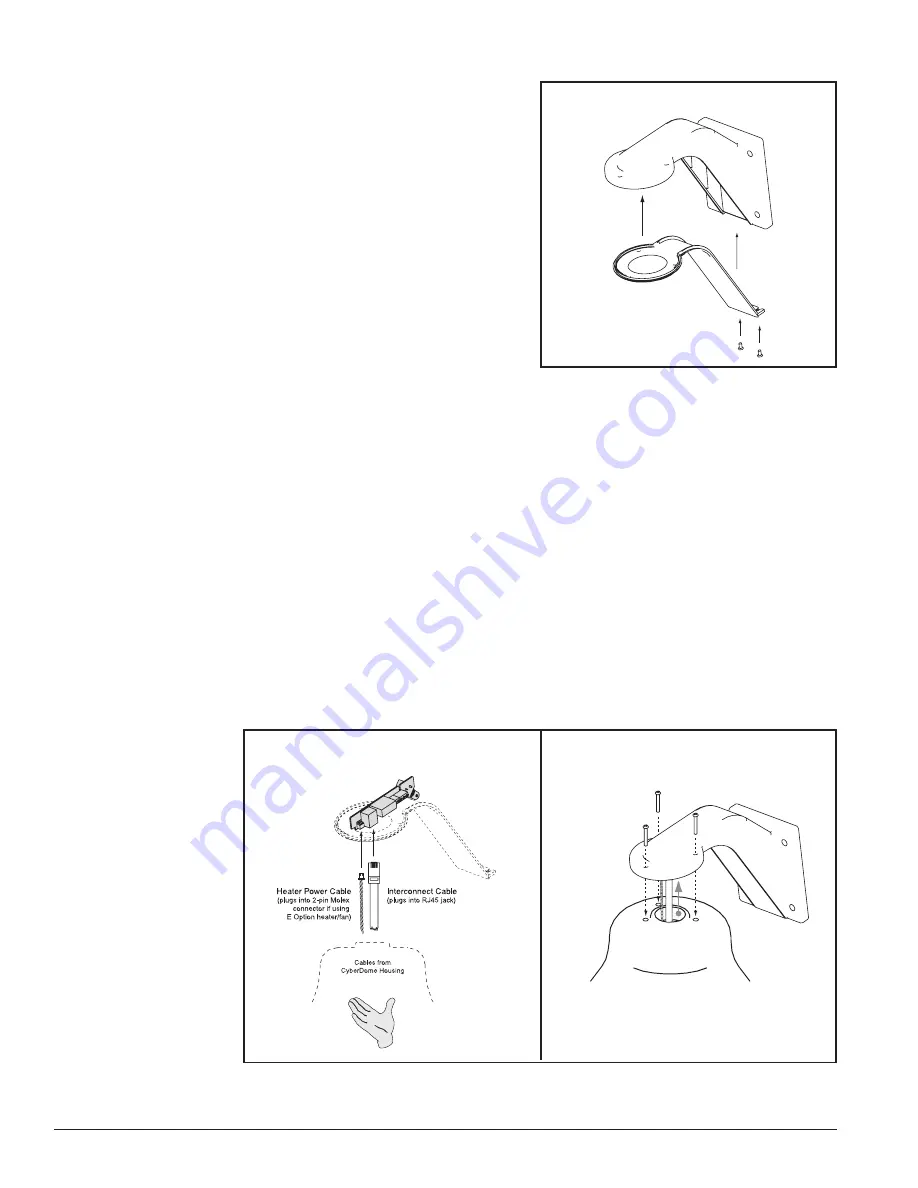
Figure 28. Fastening the Housing to the
CyberMount
Step 17)
Proceed to
RS422 Termination
on page 31.
Step 13)
Attach the CyberMount cover
with the hardware provided. See
Figure 26
.
Figure 27. Connecting the CyberDome to the
Interface Module
Finally, attach the housing to the CyberMount:
Step 14)
Bring the CyberDome housing near the end of the CyberMount collar (
DO NOT
let go of the housing until after it is secured in step 16
) and insert the
CyberDome interconnect cable into the RJ45 jack on the interface module. See
Figure 27
.
Step 15)
If installing the optional heater/fan (E option), also connect the heater’s power
cable to the 2-pin Molex connector on the module.
DO NOT let go of the hous-
ing until after it is secured in step 16.
See
Figure 27
.
The fan assembly is attached separately inside the housing to the PTZ assem-
bly. Refer to
E Option (Heater/Fan)
in
Appendix A
.
Step 16)
Guide the flange of the housing into the collar of the CyberMount (matching up
the mating holes) and fasten the housing to the CyberMount using the three
10-32x1 screws provided. See
Figure 28
.
Tighten the screws securely.
Figure 26. Attaching the CyberMount Cover
Содержание CyberDome Series
Страница 1: ...CyberDome Series Installation Manual ...
Страница 36: ...PTZ and Dome Installation CyberDome Series Installation Manual 36 A06 8SG0 B April2006 1033921C ...
Страница 44: ...Appendix A Accessory Installation CyberDome Series Installation Manual 44 A06 8SG0 B April2006 1033921C ...
Страница 46: ...Appendix B Handling Mirrored Domes CyberDome Series Installation Manual 46 A06 8SG0 B April2006 1033921C ...