MB95630H Series
MN702-00009-1v0-E
FUJITSU SEMICONDUCTOR LIMITED
249
CHAPTER 14 LIN-UART
14.7 Registers
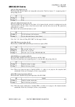
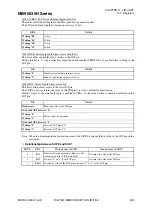
[bit4] RDRF: Receive data register full flag bit
This flag bit shows the status of the LIN-UART receive data register (RDR).
This bit is set to "1" when received data is loaded into RDR, and cleared to "0" by reading the receive data
register (RDR).
When both the RDRF bit and the RIE bit are "1", a receive interrupt request is output.
[bit3] TDRE: Transmit data register empty flag bit
This flag bit shows the status of the LIN-UART transmit data register (TDR).
This bit is set to "0" by writing the transmit data to TDR, and indicates that the TDR has valid data. When
data is loaded into the transmit shift register and data transfer starts, this bit is set to "1", indicating that the
TDR does not have valid data.
When both the TDRE bit and the TIE bit are "1", a transmit interrupt request is output.
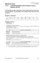
When the TDRE bit is "1", setting the LBR bit in the LIN-UART extended communication control register
(ECCR) to "1" changes the TDRE bit to "0". After the LIN synch break is generated, the TDRE bit returns to
"1".
Note: The initial value of the TDRE bit is "1".
[bit2] BDS: Transfer direction select bit
This bit specifies whether serial data transfer starts from the least significant bit (LSB-first, BDS = 0) or from
the most significant bit (MSB-first, BDS = 1).
Note: When data is written to or read from the serial data register, the data on the upper side and that on the
lower side are swapped. Therefore, if the BDS bit is modified after data is written to the RDR register,
the data in the RDR register becomes invalid. In operating mode 3 (LIN), the BDS bit is fixed at "0".
[bit1] RIE: Receive interrupt request enable bit
This bit enables or disables the receive interrupt request output to the interrupt controller.
When both the RIE bit and the receive data flag bit (RDRF) are "1", or when one or more error flag bits (PE,
ORE, FRE) is "1", a receive interrupt request is output.
[bit0] TIE: Transmit interrupt request enable bit
This bit enables or disables the transmit interrupt request output to the interrupt controller.
When both the TIE bit and the TDRE bit are "1", a transmit interrupt request is output.
bit4
Details
Reading "0"
Indicates that there is no data in the receive data register (RDR).
Reading "1"
Indicates that there is data in the receive data register (RDR).
bit3
Details
Reading "0"
Indicates that there is data in the transmit data register (TDR).
Reading "1"
Indicates that there is no data in the transmit data register (TDR).
bit2
Details
Writing "0"
Selects LSB-first. (Serial data transfer starts from the LSB.)
Writing "1"
Selects MSB-first. (Serial data transfer starts from the MSB.)
bit1
Details
Writing "0"
Disables the receive interrupt.
Writing "1"
Enables the receive interrupt.
bit0
Details
Writing "0"
Disables the transmit interrupt.
Writing "1"
Enables the transmit interrupt.
Содержание MB95630H Series
Страница 2: ......
Страница 4: ......
Страница 8: ...iv ...
Страница 20: ...xvi ...
Страница 106: ...MB95630H Series 86 FUJITSU SEMICONDUCTOR LIMITED MN702 00009 1v0 E CHAPTER 6 I O PORT 6 2 Configuration and Operations ...
Страница 282: ...MB95630H Series 262 FUJITSU SEMICONDUCTOR LIMITED MN702 00009 1v0 E CHAPTER 14 LIN UART 14 8 Notes on Using LIN UART ...
Страница 642: ...MB95630H Series 622 FUJITSU SEMICONDUCTOR LIMITED MN702 00009 1v0 E APPENDIX A Instruction Overview A 5 Instruction Map ...
Страница 644: ......


