MB95630H Series
164
FUJITSU SEMICONDUCTOR LIMITED
MN702-00009-1v0-E
CHAPTER 11 8/16-BIT COMPOSITE TIMER
11.14 Registers
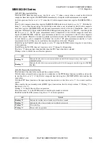
[bit6] HO: Timer suspend bit
This bit suspends or resumes the timer operation.
Writing "1" to this bit during timer operation suspends the timer operation.
When the timer operation has been enabled (Tn0CR1/Tn1CR1:STA = 1), writing "0" to the bit resumes the
timer operation.
With the PWM timer function (variable-cycle mode) in use (Tn0CR0/Tn1CR0:F[3:0] = 0b0100), the HO bit
in either Tn0CR1 (timer n0) or Tn1CR1 (timer n1) can be used to suspend or resume timer operation. If the
HO bit in one of the registers is set to "0" or "1", the HO bit in the other one is automatically set to the same
value.
In 16-bit operation (TMCRn:MOD = 1), use the HO bit in the Tn0CR1 (timer n0) register to suspend or
resume timer operation. If the HO bit in one of the registers is set to "0" or "1", the HO bit in the other one is
automatically set to the same value.
[bit5] IE: Interrupt request enable bit
This bit enables or disables the output of interrupt requests.
Writing "0" to this bit disables the interrupt request.
Writing "1" to this bit outputs an interrupt request when the pulse width measurement completion/edge
detection flag (Tn0CR1/Tn1CR1:IR) or timer reload/overflow flag (Tn0CR1/Tn1CR1:IF) is "1".
However, an interrupt request from the timer reload/overflow flag (Tn0CR1/Tn1CR1:IF) is not output unless
the IF flag interrupt enable bit (Tn0CR0/Tn1CR0:IFE) is also set to "1".
[bit4] IR: Pulse width measurement completion/edge detection flag
This bit indicates the completion of pulse width measurement or the detection of an edge.
Writing "0" to this bit sets it to "0".
Writing "1" to this bit has no effect on operation.
With the PWC timer function in use, this bit is set to "1" immediately after pulse width measurement is
complete.
With the input capture function in use, this bit is set to "1" immediately after an edge is detected.
The bit is set to "0" when the function of the composite timer selected is neither the PWC timer function nor
the input capture function.
When read by the read-modify-write (RMW) type of instruction, this bit always returns "1".
The IR bit in the Tn1CR1 (timer n1) register is set to "0" in 16-bit operation.
bit6
Details
Writing "0"
Resumes the timer operation.
Writing "1"
Suspends the timer operation.
bit5
Details
Writing "0"
Disables the interrupt request.
Writing "1"
Enables the interrupt request.
bit4
Details
Reading "0"
Indicates that the pulse width measurement has been completed or no edge has been detected.
Reading "1"
Indicates that the pulse width measurement has been completed or an edge has been detected.
Writing "0"
Clears this flag.
Writing "1"
Has no effect on operation.
Содержание MB95630H Series
Страница 2: ......
Страница 4: ......
Страница 8: ...iv ...
Страница 20: ...xvi ...
Страница 106: ...MB95630H Series 86 FUJITSU SEMICONDUCTOR LIMITED MN702 00009 1v0 E CHAPTER 6 I O PORT 6 2 Configuration and Operations ...
Страница 282: ...MB95630H Series 262 FUJITSU SEMICONDUCTOR LIMITED MN702 00009 1v0 E CHAPTER 14 LIN UART 14 8 Notes on Using LIN UART ...
Страница 642: ...MB95630H Series 622 FUJITSU SEMICONDUCTOR LIMITED MN702 00009 1v0 E APPENDIX A Instruction Overview A 5 Instruction Map ...
Страница 644: ......


