MB95630H Series
202
FUJITSU SEMICONDUCTOR LIMITED
MN702-00009-1v0-E
CHAPTER 14 LIN-UART
14.2 Configuration
●
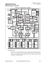
Receive control circuit
This block consists of a receive bit counter, a start bit detection circuit, and a receive parity
counter. The receive bit counter counts the receive data bits and sets a flag in the LIN-UART
receive data register when the reception of one data is completed according to the specified
data length. If the receive interrupt has been enabled, a receive interrupt request is made. The
start bit detection circuit detects a start bit in a serial input signal. When a start bit is detected,
the circuit sends a signal to the reload counter in synchronization with the start bit falling edge.
The receive parity counter calculates the parity of the received data.
●
Receive shift register
The circuit captures received data from the SIN pin while performing bit shifting of received
data. The receive shift register transfers received data to the RDR register.
●
LIN-UART receive data register (RDR)
This register retains the received data. Serial input data is converted and stored in the LIN-
UART receive data register.
●
Transmit control circuit
This block consists of a transmit bit counter, a transmit start circuit, and a transmit parity
counter. The transmit bit counter counts the transmit data bits and sets a flag in the transmit
data register when the transmission of one data is completed according to the specified data
length. If the transmit interrupt has been enabled, a transmit interrupt request is made. The
transmit start circuit starts transmission when data is written to the TDR. The transmit parity
counter generates a parity bit for data to be transmitted if the data has a parity.
●
Transmit shift register
Data written to the LIN-UART transmit data register (TDR) is transferred to the transmit shift
register, and then the transmit shift register outputs the data to the SOT pin while performing
bit shifting of the data.
●
LIN-UART transmit data register (TDR)
This register sets the transmit data. Data written to this register is converted to serial data and
then output.
●
Error detection circuit
This circuit detects errors occurring at the end of reception. If an error occurs, a corresponding
error flag is set.
●
Oversampling circuit
In asynchronous mode, the oversampling circuit oversamples received data for five times to
determine the received value by majority of sampling values. The circuit stops operating in
synchronous mode.
●
Interrupt generation circuit
This circuit controls all interrupt sources. An interrupt is generated immediately provided that
the corresponding interrupt enable bit has been set.
Содержание MB95630H Series
Страница 2: ......
Страница 4: ......
Страница 8: ...iv ...
Страница 20: ...xvi ...
Страница 106: ...MB95630H Series 86 FUJITSU SEMICONDUCTOR LIMITED MN702 00009 1v0 E CHAPTER 6 I O PORT 6 2 Configuration and Operations ...
Страница 282: ...MB95630H Series 262 FUJITSU SEMICONDUCTOR LIMITED MN702 00009 1v0 E CHAPTER 14 LIN UART 14 8 Notes on Using LIN UART ...
Страница 642: ...MB95630H Series 622 FUJITSU SEMICONDUCTOR LIMITED MN702 00009 1v0 E APPENDIX A Instruction Overview A 5 Instruction Map ...
Страница 644: ......


