


Table 3.3-2 Control Terminals
Converter stack
Item
Name
Specifications
Input
s
igna
ls
RUN/STOP command
[RUN]
Connect across RUN and CM to boost the voltage, or disconnect to stop.
Alarm reset command
[RST]
After removing the cause of the alarm upon alarm stop, connect across
RST and CM to cancel protection and restart operation.
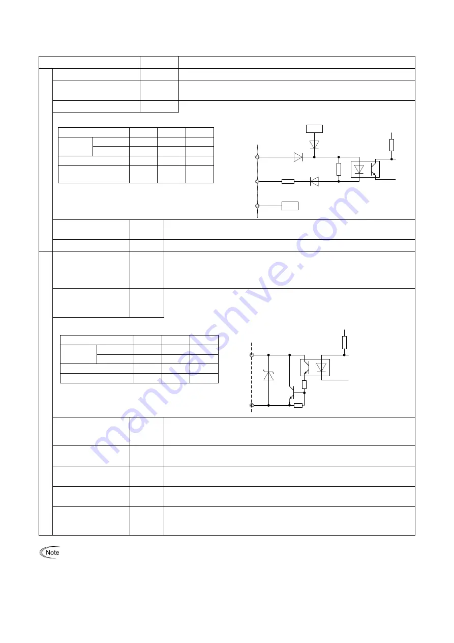
Digital input
[X1]
Digital input circuit specification
0V
+24V
6.8k
Ω
PLC
RUN,X1,RST
CM
PLC signal power
supply
[PLC]
Connect the power supply of the PLC output signals. (Rated voltage 24 (22 to
27) VDC)
Digital input common
[CM]
Common terminal for digital input signals
O
ut
put
s
igna
ls
Alarm output
[30A]
[30B]
[30C]
Signal is output upon alarm stop after the protective function of the converter
is activated.
(Contact: 1C. Upon alarm, ON across 30A and 30C)
(Contact capacity: 250 VAC 0.3A cos
θ
= 0.3)
General-purpose
transistor output
(Standard: 3 points)
[Y1]
[Y2]
[Y3]
Transistor output circuit specification
28-30V
Y1-Y3
CME
General-purpose
transistor output
common
[CME]
Common terminal for transistor output signals. Isolated from terminals CM.
Relay output
(Standard: 1 point)
[Y5A]
[Y5C]
Signal can be selected similarly to Y1 to Y3 terminals.
The contact capacity is the same as that of the batch alarm output.
General-purpose
analog output
[AO1]
Outputs monitor signals of analog DC voltage (0 to ±10 VDC).
Analog output
common
[M]
Common terminal for analog output terminals
Charging circuit
control output
[73A]
[73C]
Output for controlling external charging circuit
Connect the electromagnetic contactor included in standard accessories.
(Contact capacity: 250 VAC 5A max.)
Terminals [Y5A/C] and [30A/B/C] and [73A/C] use mechanical contacts that cannot stand frequent ON/OFF
switching. Frequent ON / OFF switching signals can be output from the transistor outputs terminals [Y1]
‐
[Y3].
Further, even if an AC power source, in the case of loads, such as direction of the contact current is fixed (such as
load having a half-wave rectifier circuit, for example a timer, the power supply for the motor electromagnetic
brake), contact life is shortened. In such a case, instead of directly connecting the load to the contact output
terminal, the control relay (separately installed) that matches the load requirement is connected to the contact output
terminal, and connected to the load via the relay.
Item
min.
typ.
max.
Operating
voltage
ON level
0 V
-
2 V
OFF level
22 V
22 V
27 V
Operating current at ON
-
3.2 mA 4.5 mA
Allowable leakage
current at OFF
-
-
0.5 mA
Item
min.
typ.
max.
Operating
voltage
ON level
-
1 V
2 V
OFF level
-
24 V
27 V
Max. load current at ON
-
-
50 mA
Leakage current at OFF
-
-
0.1 mA
3-7
Содержание RHC-D 690V Series
Страница 8: ...Location of General Precaution and Warning Labels PWM Converter RHC D Series vi...
Страница 153: ...10 3 External Dimensions Rank 3 Converter stack RHC132S 69DE RHC160S 69DE RHC200S 69DE 10 4...
Страница 154: ...Rank 4 Converter stack RHC250S 69DE RHC280S 69DE RHC315S 69DE RHC355S 69DE RHC400S 69DE RHC450S 69DE 10 5...


