7 Electric components and wiring
7.1 PLC
The controller consists of a main electrical cabinet and two expansion switch cabinets. The CPU and display
unit are installed in the main electrical cabinet. Additional connections to system components or a customer's
own control system are wired to the main control cabinet.
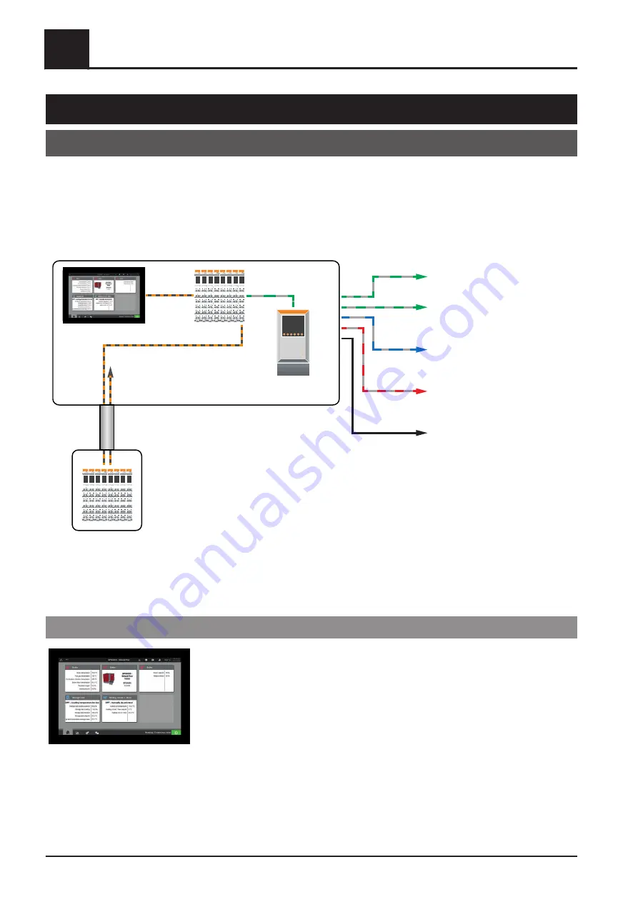
The following diagram shows the basic structure of the control system:
X2X-Link
X2X-Link
ModBus
ModBus
ModBus
M-Bus
Ethernet
Main electrical cabinet
Expansion
control cabinet
(optional)
Cascade
ModBus customer
(control system)
External components
(discharge, etc.)
Meter bus (heat meter)
LAN
Frequency converter
7.1.1 Touchscreen
Power panel C80, 10.1" capacitive touchscreen with glass front, Intel Atom 1600 Mhz,
4 GByte DDRAM, 2 GByte flash drive on board, 1x Ethernet interface 10/100, 1x X2X
link, 1x Powerlink interface, 2x USB 3.0
7
Electric components and wiring
PLC
90
Fröling GesmbH | A-4710 Grieskirchen, Industriestraße 12 | www.froeling.com
Содержание SPS 4000
Страница 114: ...7 Electric components and wiring PLC 114 Fröling GesmbH A 4710 Grieskirchen Industriestraße 12 www froeling com ...
Страница 142: ...8 Notes 8 Notes 142 Fröling GesmbH A 4710 Grieskirchen Industriestraße 12 www froeling com ...
Страница 143: ...Notes 8 Service manual SPS 4000 B0960622_en 143 ...


