Air flap secondary1 stop 0% opening
If the value is below this, the flap is detected as being
closed. Due to tolerances in the return signal, a closed flap
may return an opening of a few %.
Air flap secondary1 stop 100% opening
If the value is above this, the flap is detected as being
open. Due to tolerances in the return signal, an open flap
may return an opening of just under 100%.
Air flap tertiary1 stop 0% opening
If the value is below this, the flap is detected as being
closed. Due to tolerances in the return signal, a closed flap
may return an opening of a few %.
Air flap tertiary1 stop 100% opening
If the value is above this, the flap is detected as being
open. Due to tolerances in the return signal, an open flap
may return an opening of just under 100%.
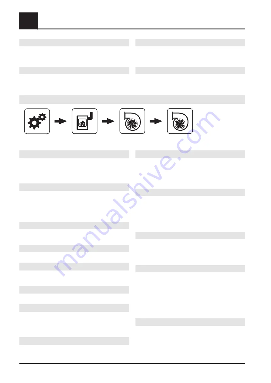
FGR
System menu
Boiler
Air damper/blower fan
FGR
Release FGR flue gas temperature
Flue gas temperature at or above which the flue gas
recirculation control system is activated. If the flue gas
temperature falls to a level 3 °C below this value, then the
FGR will be deactivated.
Release FGR combustion chamber temperature
Specifies the value in percent of the combustion chamber
signal at or above which the flue gas recirculation is
activated. If the combustion chamber temperature falls so
low that the CCT signal falls below this value again, the
flue gas recirculation will be deactivated again.
FGR compressed air cleaner interval
When the compressed air cleaner of the FGR fan is
activated, cleaning is started during this interval.
FGR compressed air cleaner duration
This is how long cleaning of the FGR fan is active for.
FGR cleaning active?
Allows the FGR primary air channel to be cleaned
automatically based on the boiler status FGR run-on.
FGR cleaning duration
Duration of automatic cleaning of FGR air duct.
Min. FGR control for FGR start
The FGR is only activated when demand equals or
exceeds this value. If the flue gas temperature drops by
the value set for FGR hysteresis after the FGR is
activated, the FGR is deactivated again.
Residual oxygen reduction in FGR mode
Specifies the maximum reduction to the residual oxygen
content in percent that can be made FGR mode.
Start residual oxygen reduction in FGR mode
Specifies start point for reduction of the residual oxygen
content as a percentage of the combustion chamber
control band. The control band is defined by the
parameters "0% CCT signal at CCT" and "100% CCT
signal at CCT".
Stop residual oxygen reduction in FGR mode
Specifies the stop point for reduction of the residual
oxygen content as a percentage of the combustion
chamber control band. The control band is defined by the
parameters "0% CCT signal at CCT" and "100% CCT
signal at CCT". The maximum possible reduction of the
residual oxygen content is reached from this time.
CCT signal for primary FGR start
Specifies the start point for the FGR primary air as a
percentage of the combustion chamber control band. The
control band is defined by the parameters "0% CCT signal
at CCT" and "100% CCT signal at CCT".
CCT signal for primary FGR stop
Specifies the stop point for the FGR primary air as a
percentage of the combustion chamber control band. The
control band is defined by the parameters "0% CCT signal
at CCT" and "100% CCT signal at CCT". Because the
FGR primary air is also dependent on the instantaneous
feed level, it is important that the FGR primary air flap is
not yet at its maximum position when this point is reached
or exceeded.
Max. control of FGR primary air flap
Defines the maximum opening of the FGR primary air flap
and serves to limit the proportion of FGR primary air.
5
Menus and parameters
Boiler
44
Fröling GesmbH | A-4710 Grieskirchen, Industriestraße 12 | www.froeling.com
Содержание SPS 4000
Страница 114: ...7 Electric components and wiring PLC 114 Fröling GesmbH A 4710 Grieskirchen Industriestraße 12 www froeling com ...
Страница 142: ...8 Notes 8 Notes 142 Fröling GesmbH A 4710 Grieskirchen Industriestraße 12 www froeling com ...
Страница 143: ...Notes 8 Service manual SPS 4000 B0960622_en 143 ...


