


ELECTRICAL INSTALLATION
Control Circuit Connections
44
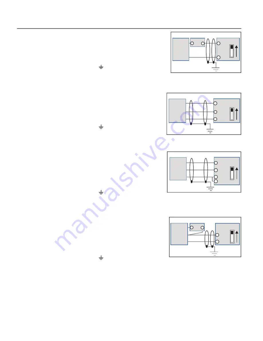
4-20mA Transducer with External 24 VDC Power
•
Connect the transducer positive (Power) wire to the external source positive
[+24V]. Connect the external source negative to the VFD ACM terminal.
•
Connect the transducer output (Out) wire to the ACI or AVI1 terminal. The ACI
micro switch should be in the up position. If using the AVI1 terminal, the AVI1 micro
switch should be down.
•
Any shield wire should be connected to Earth ground.
•
ACI Input Sel [IO–00]
or
AVI1 Input Sel [IO–05]
should be set to the correct signal type.
•
Auto Speed Ref [SET–07]
should be set to
PID Output
,
PID F/B Source [SET–18]
should be set to the chosen input,
and
PID F/B Unit [SET–19]
should be set to the appropriate scale (psi, temp, flow, etc.).
0-10VDC Transducer with VFD 10 VDC Power
•
Connect the transducer positive (Power) wire to the VFD +10V terminal.
•
Connect the transducer output (Out) wire to the AVI1, AVI2, or ACI terminal. The
AVI1 micro switch should be in the up position. If using the ACI terminal, the ACI
micro switch should be down.
•
Connect the transducer Com wire to the ACM terminal (signal ground).
•
Any shield wire should be connected to Earth ground.
•
ACI Input Sel [IO–00]
or
AVI1 Input Sel [IO–05]
should be set to
0-10V
.
•
Auto Speed Ref [SET–07]
should be set to
PID Output
,
PID F/B Source [SET–18]
should be set to the chosen input,
and
PID F/B Unit [SET–19]
should be set to the appropriate scale (psi, temp, flow, etc.).
0-10VDC Transducer with VFD 24 VDC Power
•
Connect the transducer positive (Power) wire to the VFD +24V terminal.
•
Connect the transducer output (Out) wire to the AVI1, AVI2, or ACI terminal. The
AVI1 micro switch should be in the up position. If using the ACI terminal, the ACI
micro switch should be down.
•
Connect the transducer Com wire to the ACM terminal (signal ground).
•
Use a jumper wire to connect the ACM and DCM terminals.
•
Any shield wire should be connected to Earth ground.
•
ACI Input Sel [IO–00]
or
AVI1 Input Sel [IO–05]
should be set to
0-10V
.
•
Auto Speed Ref [SET–07]
should be set to
PID Output
,
PID F/B Source [SET–18]
should be set to the chosen input,
and
PID F/B Unit [SET–19]
should be set to the appropriate scale (psi, temp, flow, etc.).
0-10VDC Transducer with External 24 VDC Power
•
Connect the transducer positive (Power) wire to the external source positive
[+24V].
•
Connect the transducer Com wire to the external source negative.
•
Connect the transducer output (Out) wire to the AVI1, AVI2, or ACI terminal. The
AVI1 micro switch should be in the up position. If using the ACI terminal, the ACI
micro switch should be down.
•
Any shield wire should be connected to Earth ground.
•
ACI Input Sel [IO–00]
or
AVI1 Input Sel [IO–05]
should be set to
0-10V
.
•
Auto Speed Ref [SET–07]
should be set to
PID Output
,
PID F/B Source [SET–18]
should be set to the chosen input,
and
PID F/B Unit [SET–19]
should be set to the appropriate scale (psi, temp, flow, etc.).
Transducer
Power (+)
Out
Power Supply
+ -
VFD
ACM
ACI
ACI
Shield
Transducer
Power (+)
Out
Com
VFD
AVI1
AVI1
ACM
+10V
Shield
VFD
+24V
AVI1
ACM
DCM
Power (+)
Out
Com
AVI1
Transducer
Shield
Transducer
Power (+)
Com
Out
Power Supply
+ -
VFD
AVI1
ACM
Shield
AVI1
Содержание CERUS X-DRIVE CXD-003A-4V
Страница 1: ...franklin electric com ENGLISH EN CERUSX DRIVE Installation and Operation Manual Firmware Version 1 2 ...
Страница 2: ......
Страница 3: ...CERUS X DRIVE INSTALLATION AND OPERATION MANUAL Firmware Version 1 2 Franklin Electric Co Inc ...
Страница 96: ...OPERATION Protection Features 96 ...
Страница 112: ...ADVANCED APPLICATION OPTIONS Multi Drive Configurations 112 ...
Страница 124: ...COMMUNICATIONS BACnet Communication 124 ...
Страница 128: ...ACCESSORIES Optional Extension Cards 128 Frame D Frame E Frame F ...
Страница 129: ...ACCESSORIES Optional Extension Cards 129 Frame G Frame H ...
Страница 132: ...ACCESSORIES Optional Extension Cards 132 ...
Страница 234: ...PARAMETER REFERENCE TABLES Parameter Descriptions Motor Menu 234 ...
Страница 250: ...GLOSSARY 250 ...
Страница 252: ...For technical assistance parts or repair please contact 800 348 2420 franklin electric com 10000005064 Rev 004 09 22 ...