Format kappa 30 Скачать руководство пользователя страница 32

Panel Saw 

Kappa 30 / kappa 40

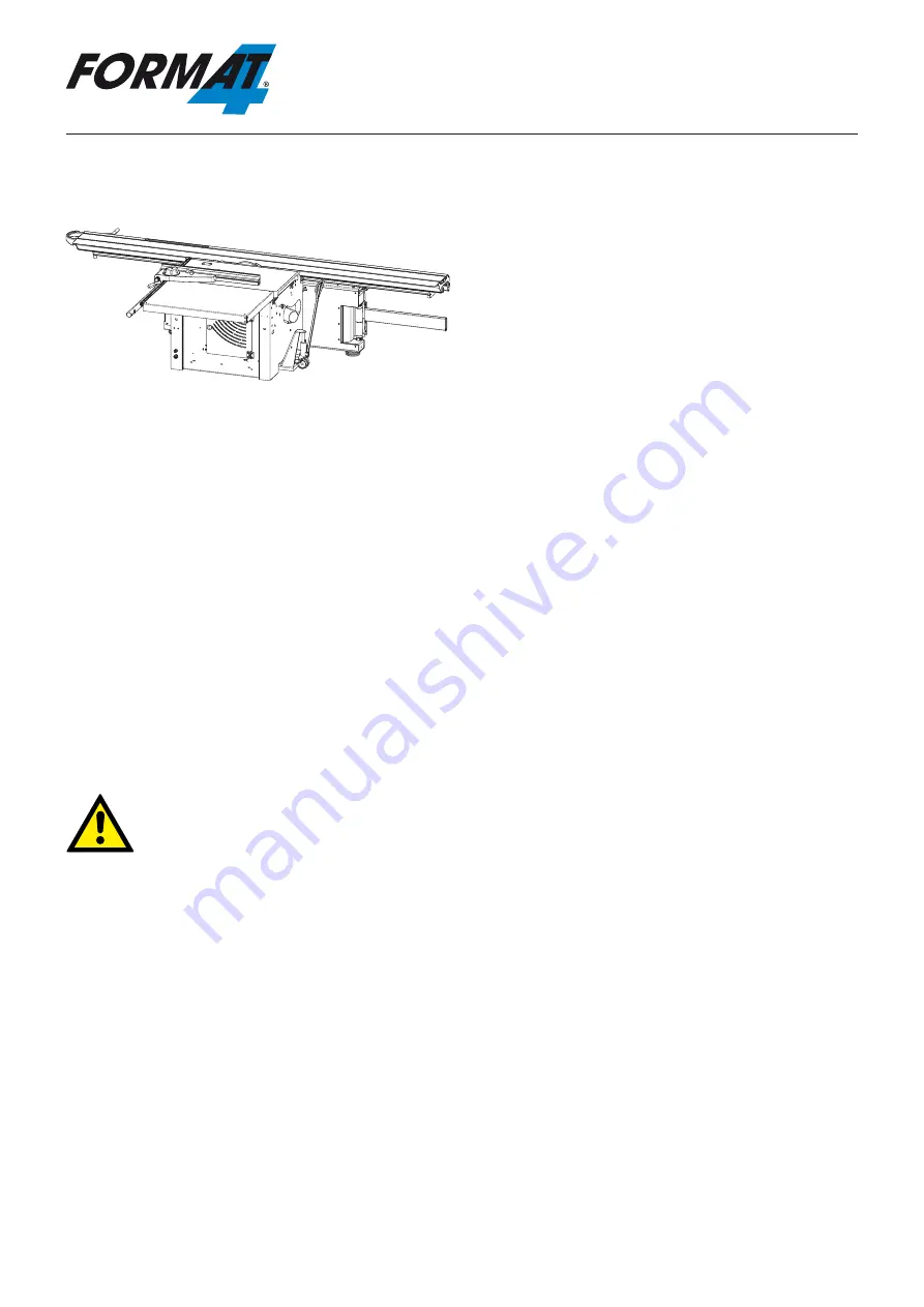
6.2.4.2 Transporting the machine

Fig. 26: Transport with a pallet jack

Push the pallet jack forks into the holes of the machine 

frame. 

6.3 Transport inspection

Upon arrival, inspect the shipment to ensure that it is 

complete and has not suffered any damage.

If any transport damage is visible, do not accept the de-

livery or accept it only with reservation. Record the scope 

of the damage on the transport documents/delivery note. 

Initiate the complaint process.

For all defects that are not discovered upon delivery, be 

sure to report them as soon as they are recognized be-

cause claims for damages must be filed within a certain 

period, as granted by law.

6.4 Packaging

If no agreement has been made with the supplier to take 

back the packaging materials, help to protect the envi-

ronment by reusing the materials or separating them ac-

cording to type and size for recycling.

Attention! Dispose of the packaging materials in an environmentally friendly way and always in accord-

ance with local waste disposal regulations. If applicable, contract a recycling firm to dispose of the pack-

aging materials.

Attention: Help preserve the environment! Packaging materials are valuable raw materials and in many 

cases they can be used again or expediently reprocessed or recycled.

Transport, packaging and storage

32

Содержание kappa 30

Страница 1: ...User Manual Panel Saws kappa 30 kappa 40 Keep this manual handy and in good condition for continual reference Dok ID 431010 903_02 Englisch 2011 11 22 Translation...

Страница 2: ...pt to hand and within the vicinity of the machine so that it is accessible to operators when using maintaining or repairing the machine FORMAT 4 A product of the FELDER GROUP Note Year of construction...

Страница 3: ...ructions 13 3 Declaration of Conformity 14 4 Technical specifications 15 4 1 Dimensions and weight 15 4 2 Saw unit 16 4 3 Scoring unit 16 4 4 Operation and storage conditions 16 4 5 Drive motor 16 4 6...

Страница 4: ...Scale track 37 7 3 4 Bar 37 7 3 5 Cutting extension 38 7 4 Dust extraction system 39 7 5 Electrical connection 40 8 Making adjustments and preparations 41 8 1 Safety instructions 41 8 2 Sliding table...

Страница 5: ...machine 67 9 4 EMERGENCY STOP 68 9 5 Moving the sliding table 68 9 6 Work stations 69 9 7 Working techniques 69 9 7 1 Authorised working techniques 69 9 7 2 Prohibited working techniques 70 9 7 3 Gene...

Страница 6: ...hanging the battery of the sliding table remote ON switch 85 11 7 Changing the cross stop battery 86 11 8 Changing the rip fence battery 86 11 9 Correcting the rip fence angle 87 11 10 Readjusting the...

Страница 7: ...Warning Danger Electric current This symbol warns of potentially dangerous situations related to electric current Not observing the safety instructions increases the risk of serious injury or death A...

Страница 8: ...those persons who work on or with the machine All descriptions texts drawings photos and other depictions are protected by copyright and other commercial laws Illegal use of the materials is punishab...

Страница 9: ...el and can therefore be dismantled without difficulties This material is also easy to dispose of and does not Attention Used electrical materials electronic components lubricants and other auxiliary s...

Страница 10: ...regarding damage resulting from improper use that are made against the manufacturer and its authorised representatives shall be rejected The operator alone is responsible for all damages incurred as...

Страница 11: ...delegated tasks and recognise potential risks If the personnel lack the necessary knowledge for work ing on or with the machine they must first be trained Responsibility for working with the machine...

Страница 12: ...avoid hearing damage 2 8 Machine hazards The machine has undergone a hazard analysis The design and construction of the machine are based on the results of this analysis and correspond to state of th...

Страница 13: ...e machine units require batteries Warning Risk of injury Swallowing batteries is a health hazard Keep bat teries out of reach of children Seek medical care immediately if you have swallowed a battery...

Страница 14: ...s certified by EG Design Test Certificate No HO 101026 EG Declaration of Conformity according to Machine Guidelines 2006 42 EG We hereby declare that the machine indicated below which corresponds to t...

Страница 15: ...ing table cutting width 800 mm B 1150 mm 1150 mm 1150 mm 1150 mm Sliding table cutting width 1250 mm B 1600 mm 1600 mm 1600 mm 1600 mm Outrigger C 3360 mm 3360 mm 3360 mm 3360 mm Machine Standard Opti...

Страница 16: ...pindle 30 mm 30 mm Speed 50 Hz fixed 4800 min 1 3500 4500 5500 min 1 Speed 50 Hz infinitely variable 3000 6000 min 1 Cutting height at max Saw blade at 45 90 73 5 104 mm 94 133 mm Saw blade tiltable f...

Страница 17: ...alues may deviate significantly from the specified values Attention To keep the noise emission as low as possible always used sharpened tools and use the correct speed Ear protection must always be wo...

Страница 18: ...ction Overhead saw guard Saw guard Outlet size Unit 120 mm 120 mm Outlet size Overhead saw guard and saw guard 80 mm 50 mm Air speed min 20 m s 20 m s Vacuum min 1200 Pa 1400 Pa Volume flow min at 20...

Страница 19: ...iew Fig 2 Overview Crosscut fence Outrigger table Sliding table Splitter and Saw blade Overhead saw guard with dust extraction 80 mm Machine table Parallel cutting fence Remote ON switch on sliding ta...

Страница 20: ...le extension Sliding table extension For exact parallel cuts in particular for long workpieces Assembly instructions Equipment for parallel cuts Equipment for parallel cuts 5 2 Accessories Fig 4 Slidi...

Страница 21: ...centric clamp Art No 600 07100 Side hand lever Art No 601 102 To move the sliding table more easily Assembly instruc tions Side hand lever Side hand lever To record the number of operating hours Assem...

Страница 22: ...Double mitre gauge Fig 8 Double mitre gauge To facilite the assembly of the outrigger table and to store further accessories Assembly instructions Transport and mounting unit for the outrigger table...

Страница 23: ...rd Assembly instructions Overhead saw guard Overhead saw guard Fig 10 Overhead saw guard Mounting flange group for grooving tools Art No 430 007 022 430 007 023 Kr retaining flange 430 007 076 Kr reta...

Страница 24: ...be secured with 3 padlocks The machine is equipped with a motor protection device that switches the machine off in the event of an overload Main switch 5 4 Main switch Fig 13 Main switch 5 3 Data plat...

Страница 25: ...emergency Release the EMERGENCY STOP button by turning it EMERGENCY STOP button Fig 14 EMERGENCY STOP button 5 5 Safety devices 5 5 1 EMERGENCY STOP button 5 5 2 Sliding table locking system The slidi...

Страница 26: ...guard Fig 17 Circular saw guard The overhead saw guard has to be installed and set cor rectly The dust has to be extracted from the overhead saw guard Diameter 80 mm Overhead saw guard 5 5 3 1 Overhe...

Страница 27: ...ention Risk of material damage The prog button is only for service purpose and it is only allowed to operate for FORMAT 4 Service Perso nel 5 6 1 Power Drive Green push button circular saw ON Green pu...

Страница 28: ...ontrol panel Option 3 5 6 2 Digi Drive Green push button circular saw ON Green push button Scoring unit ON Red push button machine OFF Switch Scoring unit height adjustment electronic speed display Ci...

Страница 29: ...porting it minimise the risk of it tipping over Take measures to prevent the machine from slipping sideways Ropes belts or other hoisting devices must be equipped with safety hooks Do not use torn or...

Страница 30: ...ng the machine to the installation location Transport brackets 6 2 2 Transport with a crane Only use belts or chains to transport the machine Attention Risk of material damage The machine must not be...

Страница 31: ...ansport with a pallet jack Use a loading platform similar to that depicted in the picture opposite to unload from the pallet 1 Push the pallet jack forks into the holes of the ma chine frame 2 Unload...

Страница 32: ...as soon as they are recognized be cause claims for damages must be filed within a certain period as granted by law 6 4 Packaging If no agreement has been made with the supplier to take back the packa...

Страница 33: ...bjecting the machine to shocks Storage temperature 10 to 50 C Maximum humidity 60 Avoid extreme temperature fluctuations condensation build up Apply a coat of oil to all bare machine parts corro sion...

Страница 34: ...by qualified person nel and in strict observance of the safety instructions Before assembling and installing the machine check to make sure it is complete and in good condition Warning Risk of injury...

Страница 35: ...uneven Spirit level Transport brackets 7 3 Assembly 7 3 1 Sliding table Attention Due to transport reasons the sliding table depending on its length may be packaged separate ly Two to three additiona...

Страница 36: ...osition with the adjust ment screw if required 3 Attach the overhead saw guard base to the support arm with a screw 4 Attach the overhead saw guard with screws Overhead saw guard base Overhead saw gua...

Страница 37: ...sh with the loading board 3 With a standard stop Screw the scale track tightly from the underside with a spanner 10 mm With a digital stop Screw the scale track tightly from the underside with a spann...

Страница 38: ...d of the bar slightly before screwing it to the cutting extension Washer Nut Setscrew Fig 34 Cutting extension Fig 33 Cutting extension 7 3 5 Cutting extension The cutting extensions 800 and 1250 mm a...

Страница 39: ...1110 m3 h Connecting the dust extractor to a potential free contact Option The dust extractor can be connected via the potential free contact 1 Pinch off the stranded wires flushly 2 Unscrew the thum...

Страница 40: ...kup fuse 20 A 35 A 35 A Mains voltage 400 10 V Cable cross sectional area min 2 5 mm 2 5 mm 4 0 mm Backup fuse 16 A 16 A 20 A Warnung Danger electric current Work on electrical fittings may only be ca...

Страница 41: ...r have been left lying around may be the cause of accidents Install the safety equipment according to the instruc tions and check that it functions properly 8 2 Sliding table catch Fig 37 Sliding tabl...

Страница 42: ...fence Bolts Thumb screw Fig 41 Assembling the crosscut fence Pivoting 1 Loosen the clamping lever and thumb screws 2 Pivot the crosscut fence to the desired position Fold the end stop back if necessa...

Страница 43: ...ighten the thumb screws Locking jaws Slotted round nut Fig 42 Fixing the crosscut fence 8 6 Crosscut fence Extension Fig 43 Crosscut fence Extension The crosscut fence is usually equipped with an exte...

Страница 44: ...g 44 Cross stop The cross stop can be pushed onto the crosscut fence in one movement If required the end stop can be folded back 1 Loosen the thumb screw 2 Move the cross stop to the desired position...

Страница 45: ...dge of the guide 5 Lock the clamping lever 6 Move the scale by the measurement required to adapt the scale to the different widths of the saw blade Loosen the thumb screw Move the scale Tighten the th...

Страница 46: ...el cutting fence Clamping lever Thumb screw Bar 8 8 2 Fine adjustment 1 Switch off the machine 2 Loosen the clamping lever 3 Push the setscrew down and twist 4 Lock the clamping lever following the fi...

Страница 47: ...clamping lever 2 6 Move the parallel cutting fence right up top the end of the bar 7 Swing out the parallel cutting fence Guide Setting the parallel cutting fence Clamping lever 1 Fig 52 Swinging out...

Страница 48: ...gue Only the following tools are allowed kappa 30 kappa 40 Saw blade min max 250 315 mm 250 400 350 mm Spindle 30 mm 30 mm Speed 50 Hz fixed 4800 min 1 3500 4500 5500 min 1 Speed 50 Hz continuously ad...

Страница 49: ...ol panel Option 2 8 10 2 Setting the height angle of cut Switch Scoring unit height adjustment Display Circular saw height specification Switch Circular saw angle adjustment Display Circular saw angle...

Страница 50: ...ade Socket head cap screw Attention Minimum tightening torque 20 Nm Required tools Allen key 10 mm Special spanner 1 Prepare to change tooling 2 Loosen the splitter to install a larger saw blade 3 Hol...

Страница 51: ...meter to appear in the indicator panel 6 Press The first decimal place on the indicator panel is flashinge 7 Change the value with key 3 8 The second decimal place on the indicator panel is flashing 9...

Страница 52: ...Fig 62 Speed Set 8 11 3 Speed control with a frequency changer Fig 63 Control panel Potentiometer Attention Risk of material damage Never exceed the maximum speed indicated on the tool 8 11 2 Changing...

Страница 53: ...for the overhead saw guard In addition the marking has to match the upper edge of the sliding table when the maximum cutting height is set indepently of the saw blade used Nut Space Splitter Saw blad...

Страница 54: ...red 3 Fit the splitter in Take care that the splitter holder studs fit in the split ter groove 4 Adjust the splitter Nut Splitter Use the overhead saw guard with saw blades with a diameter measuring m...

Страница 55: ...stud forwards with the thumb nut 3 Circular saw guard Remove the saw guard and insert it into the other recess 4 Secure the thumb nut Thumb nut Circular saw guard Recess 250 300 mm Recess 300 315 mm...

Страница 56: ...allowed Scoring unit blades Diameter 120 mm Chisel 20 mm Speed 8500 min 1 8 15 Scoring unit height adjustment Fig 71 Manual height adjustment Manually Twist the setscrew with a 10 mm socket spanner Cl...

Страница 57: ...towards the sliding table Anti clockwise away from the sliding table Adjust the scoring blade so it is aligned with the saw blade Clamping screw Setscrew Setscrew Fig 72 Adjusting the side The scorin...

Страница 58: ...both parts tighten the setscrew with the Allen key in the CLOSED direction Allen key Adjusting screw Setscrew Screwdriver Fig 74 Scoring blade Adjusting the width Attention Only twist the adjusting sc...

Страница 59: ...the protector tube has to be installed to prevent resinous resi due building up Fig 76 Assembling the scoring blade 6 Only with the circular saw Kappa 40 When using a 315 mm saw blade and a 120 mm sco...

Страница 60: ...circular saw Kappa 40 Pull the lock to the front and then turn to the right until the lock snaps into place 6 Fit the protector tube and mounting nut onto the scor ing arbor 7 Place the special spann...

Страница 61: ...socket head cap screw and flange 5 Remove the saw blade 6 Remove the splitter Splitter Socket head cap screw Special spanner Flange Saw blade Allen key 7 Clamp the splitter holder with the nut 8 Remo...

Страница 62: ...groove flange tight with the spanner 15 Attention Left screw thread Screw in the socket head cap screw anti clockwise with the Allen key 16 Set the grooving tool diameter in the control panel BOSpace...

Страница 63: ...ead Loosen the left screw thread clockwise with the Al len key 4 Remove the socket head cap screw and flange 5 Remove the grooving tool 6 Remove the spacer ring from the saw blade arbor if present All...

Страница 64: ...r 11 Replace the flange 12 Hold the flange in place with a special spanner 13 Attention left screw thread Tighten the socket head cap screw anti clockwise direction with the Allen key 14 Fit splitter...

Страница 65: ...ol turns freely Ensure that each unit is rotating in the proper direc tion Keep tools for handling short and narrow workpieces close at hand Before switching on the machine always check to make sure t...

Страница 66: ...ed preconditions are fulfilled and any preliminary work is completed For this reason the instructions for adjusting fitting and operating see the corresponding chapters must be read before switching o...

Страница 67: ...switch 4 Circular saw Press and release the push button remote ON switch on sliding table 5 Scoring unit Press and release the push button remote ON switch on sliding table Scoring blade push button...

Страница 68: ...ide The machine is stopped automatically Release the EMERGENCY STOP button by turning it EMERGENCY STOP button Fig 94 EMERGENCY STOP button To move the sliding table use the side hand lever the grip o...

Страница 69: ...or idling mode Fig 96 Work stations Work positions 9 7 Working techniques 9 7 1 Permitted working techniques Only the following working techniques are allowed with the circular saw Only trim if using...

Страница 70: ...11 1 009 Deflector with Holding Magnets Art No 420 260 4 Setting the height angle of cut 5 Modify the overhead saw guard for angular cuts 6 Vacuum system must be connected 7 Set scoring blade if requ...

Страница 71: ...9 7 5 Longitudinal cut Fig 99 Longitudinal cut 9 7 6 Cutting battens Fig 100 Cutting battens 1 Take note of general procedures for authorised work ing techniques 2 Adjust the parallel cutting fence t...

Страница 72: ...balled into a fist 10 Pull the work piece a few millimeters away from the saw blade and move the sliding table into the initial position Precise cut 1 Lower the end stop 2 Place the work piece agains...

Страница 73: ...working with heavy work pieces and especially when working with large panels 9 7 10 Cutting with an outrigger Rough cut 1 Take note of general procedures for authorised work ing techniques 2 Move the...

Страница 74: ...g techniques 2 Adjust the rip fence to the desired position 3 Lock the sliding table into a centre position 4 Set the cutting height to a maximum of half of that of the workpiece s thickness 5 Select...

Страница 75: ...techniques 2 Set the rip fence to the desired measurement 3 Lock the sliding table into a centre position 4 Set the cutting height to a maximum of half of that of the workpiece s thickness 5 Always us...

Страница 76: ...ve been left lying around may be the cause of accidents Following the maintenance work re install the guards and check that they are functioning properly 10 2 Maintenance schedule Attention Cleaning a...

Страница 77: ...ring tracks 10 4 Lubricating the height guide of the circular saw unit Fig 110 Height guide 1 Remove the saw blade 2 Lower the circular saw unit down as far as it goes 3 Lubricate the guide track by l...

Страница 78: ...maintenance free Replace the appropriate belt immediately should tears or side tears appear during the monthly check Scoring belts Drive belt 10 5 2 Replacing the drive belt Fig 113 Lid 1 Tilt the cir...

Страница 79: ...the new belt around the scoring spindle 6 Close the lid on the back of the machine Scoring motor Scoring belts Scoring spindle Fig 114a Speed detector 4 Pull the clamping lever upwards 5 Replace the...

Страница 80: ...the nut Replace the dust brush Loosen the nuts on the outrigger arm Remove the worn out dust brush Insert and adjust the new dust brush Tighten the nut Outrigger arm Outer slider Nuts Dust brush 10 8...

Страница 81: ...screw Fig 119 Base Sliding table On the side from which the sliding table should be pushed from the base 5 Pull the sliding table from the base Base Sliding table 6 Check the roller cage scraper Unhoo...

Страница 82: ...the length of the sliding table Fig 122 Base Roller cage On the base 7 Screw the flat head screws in Allen key Stop screw Washer 3 Thread the sliding table over the roller cages 4 Slide the sliding t...

Страница 83: ...mm Take note of the 32 mm dimension of the stop screw 9 Mount the stop screw washer and nut with an Allen key 8 mm and a spanner 17 mm 10 Fit the cover on and screw the five screws on with a spanner 8...

Страница 84: ...s Strictly speaking In the event of a breakdown which creates danger for either personnel or equipment the machine should be stopped immediately by activating the emergency stop Also disconnect the ma...

Страница 85: ...just the clamping force Readjust the height of the guide Calibrating the saw blade height display Align the roller cage Disassembly Assembly Clean the outrigger arm rollers and pipe 11 5 Aligning the...

Страница 86: ...ery has to be placed against the battery chamber lid 11 8 Changing the rip fence battery Fig 127 Changing the rip fence battery Required battery 1 x Baby C 1 Switch the machine off and ensure that it...

Страница 87: ...uts 8 Assemble and clamp the fence guide 9 Swing the rip fence back 10 Check the setting and readjust if necessary Screws Nut Clamping lever 11 10 Readjusting the height of the parallel cutting fence...

Страница 88: ...is completely open 5 Place the scoring blade onto the table and remove the upper tooling half from the lower one This will prevent the retaining ring on the setscrew from being damaged 6 Remove the s...

Страница 89: ...Ensure that the safety ring sits properly on the adjust ing screw 6 Ensure that both springs are pushed down onto the headless screws and the latter are screwed tightly 7 Screw the scoring blade disc...

Страница 90: ...detector Attention Risk of material damage Do not use detergents Clean the speed detector with a dry cloth only Fig 143 Speed detector 1 Select the measuring equipment according to the desired accurac...

Страница 91: ...Cross cutting at the rip fence 72 Cross stop 44 Cutting battens 71 Cutting extension 38 Cutting smaller narrower workpieces 73 Cutting with an outrigger 73 D Dangers 12 Data plate 24 Declaration of Co...

Страница 92: ...e 45 Assembly 19 Sliding table 35 Sliding table catch 41 Sliding table locking system 25 Sliding table scraper 80 Spare parts 8 Technical specifications 15 Speed control with a frequency changer 52 Sp...

Страница 93: ......

Страница 94: ...FORMAT 4 machine construction KR FELDER STR 1 A 6060 Hall in Tirol Tel 43 0 5223 55306 Fax 43 0 5223 55306 63 E mail info format 4 com Internet www format 4 com...

Страница 95: ...delivery and payment conditions Email Address Yes please send me your Newsletter In this position is your Warranty Card After sending in your warranty card you will receive A certificate of the expan...

Страница 96: ...e send me your Newsletter Electrical Equipment V PH Hz A FORMAT 4 Qualified personnel FORMAT 4 Operation manual KW Year of Manufacture Machine Number Machine type Received on Machine was bought from C...

Отзывы: