


Wiring Notes
CAN-CBX-THERMO
Manual • Doc.-No.: C.3034.21 / Rev. 1.2
Page 37 of 123
6.2.2 Cabling
L
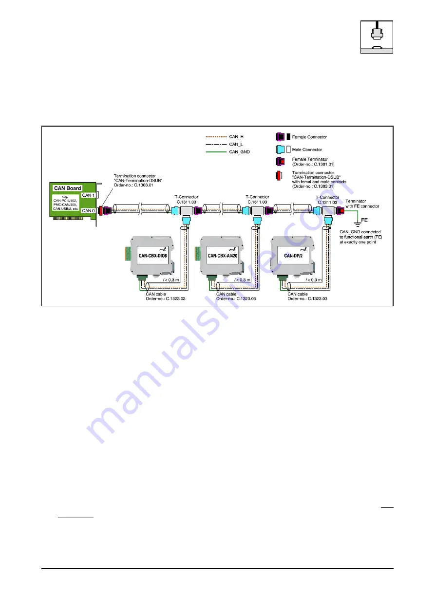
To connect CAN devices with just one CAN connector per net use a short stub (< 0.3 m) and a
T-connector (available as accessory). If this devices are located at the end of the CAN network, the
CAN terminator “CAN-Termination-DSUB9” can be used.
Figure. 15: Example for proper wiring with single shielded single twisted pair wires
6.2.3 Branching
L
In principle the CAN bus has to be realized in a line. The participants are connected to the main
CAN bus line via short cable stubs. This is normally realised by so called T-connectors. esd offers
the CAN-T-Connector (Order No.: C.1311.03)
L
If a mixed application of single twisted and double twisted cables is unavoidable, take care that
the CAN_GND line is not interrupted!
L
Deviations from the bus structure can be realized by the usage of repeaters.
6.2.4 Termination
L
A termination resistor has to be connected at both ends of the CAN bus.
If an integrated CAN termination resistor which is equipped at the CAN interface at the end of the
bus is connected, this one has to be used for termination instead of an external CAN termination
plug.
L
9-pin DSUB-termination connectors with integrated termination resistor and male and female
contacts are available from esd (order no. C.1303.01).
L
DSUB termination connectors with male contacts (order no. C.1302.01) or female contacts (order
no. C.1301.01) and additional functional earth contact are available, if CAN termination and
grounding of CAN_GND is required.