


Hardware-Installation
Manual • Doc.-No.: C.3034.21 / Rev. 1.2
CAN-CBX-THERMO
Page 28 of 123
4.4.3 Connection of CAN
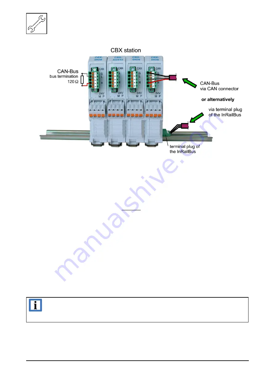
Fig. 12: Connecting the CAN signals to the CAN-CBX station
Generally the CAN signals can be fed via the CAN connector of the first CAN-CBX module of the
CBX station. The signals are then connected through the CAN-CBX station via the InRailBus. To lead
through the CAN signals through the CBX station the CAN bus connector of the last CAN-CBX
module of the CAN-CBX station has to be used. The CAN connectors of the CAN-CBX modules which
are not at the ends of the CAN-CBX station must not be connected to the CAN bus, because this would
cause incorrect branching.
A bus termination must be connected to the CAN connector of the CAN-CBX module at the end of the
CBX-InRailBus (see Fig. 12), if the CAN bus ends there.
4.5 Remove the CAN-CBX Module from the InRailBus
If the CAN-CBX module is connected to the InRailBus please proceed as follows:
Release the module from the mounting rail in moving the foot catch (see Fig. 9) downwards (e.g. with
a screwdriver). Now the module is detached from the bottom edge of the mounting rail and can be
removed.
INFORMATION
It is possible to remove individual devices from the CBX station without interrupting
the InRailBus connection, because the contact chain will not be disrupted.