


Overview
Manual • Doc.-No.: C.3034.21 / Rev. 1.2
CAN-CBX-THERMO
Page 10 of 123
!"#
$%&'
()
*
& #
+,
$ -$.
&'
/
0'&.0,
1 $%,
0%02.,0''+,
1345647
89:; <:9
=9<
<>
?@< :A
=
!0B+,
CDEE'#
F6
G
H(I
< 9=
:;
J;
K LM?
N@ ;
:;
O?LP
QRSTU
VWXYOV Z
:;
OWR STSV [\R ]
W
(^
(
(02_
+,.+,
$ -$.
&'
`+a E+,&.
D,+
C
+2
0,
$-$.&'
/
0'&.0,
LA;b :
9
=
:;
O
WcST WQ
V[ \R]W
89:; <:9
=9<
(^
(
(02_+,
.+,
Ud
L
A; b:
9 ;
=
e
f
g)^
(02_+,.
+,
1. Overview
1.1 Description of the Module
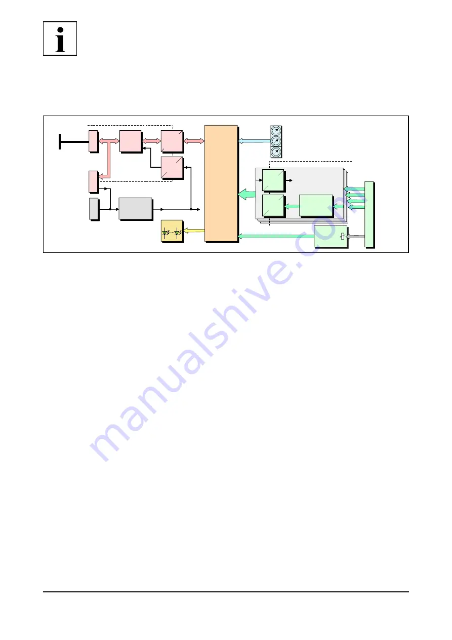
Fig. 1: Block circuit diagram of the CAN-CBX-THERMO module
The CAN-CBX-THERMO module is a CAN-CBX module with four High Resolution
Thermocouple Interfaces.
The CAN-CBX-THERMO is equipped with four independent sigma-delta A/D converters for the
evaluation of thermocouples. It features support of J, K, B, E, N, R, S and T thermocouples.
Depending on the selected sample rate and the external wiring a resolution of at least 1
h
V can be
achieved.
For cold junction compensation the temperature of the sensor clamp is measured by a digital
temperature sensor.
The conversion of the four thermocouple inputs is realized by four independent
ij
-converters.
Linearisation according to NIST is achieved by the on board microcontroller.
The CAN interface is designed according to ISO11898-2 high-speed layer with electrical isolation
and supports bit rates up to 1 Mbit/s. The CANopen-node number and the CAN-bit rate can be
easily set via coding switches.
The CAN-CBX-THERMO features the possibility to connect the power supply and the CAN bus
signals via the InRailBus connector (TBUS-connector) integrated in the mounting rail. Individual
modules can then be removed without interrupting the bus signals.
The module comes with CANopen
®
firmware according to CiA
®
301 and supports the CiA 404
profile for measuring devices.