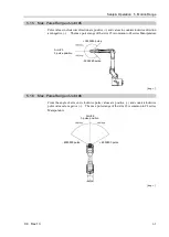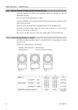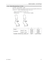
Setup & Operation 4. End Effectors
50
C8 Rev.13
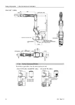
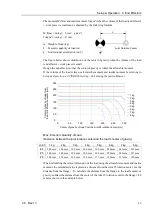
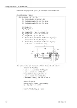
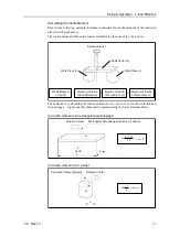
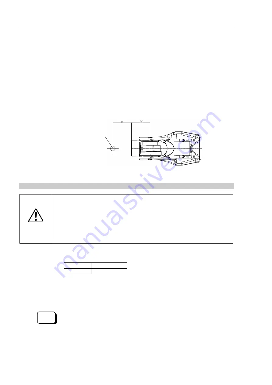
Example: Calculation of the critical dimension of the load (a) when the load is 8 kg.
Center of gravity by the allowable moment control:
16.6 N·m/(8 kg×9.8 m/s
2
) = 0.212 m = 212 mm
Center of gravity by the allowable inertia moment control:
(0.47 kgm
2
/8 kg)
1/2
= 0.242 m = 242 mm
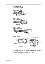
Due to the allowable moment control, center of gravity for the load limit is 212
mm from the Arm #5 rotation center.
Distance from the flange to the center of gravity for the load limit
a = 212 mm
-
80 mm = 132 mm
Critical Dimension of Load
Arm #6
Rotation Center
Load’s Center of Gravity
Flange
Arm #5
Rotation Center
[Unit: mm]
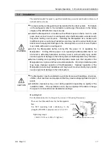
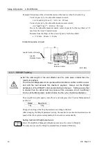
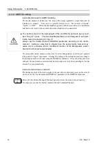
4.3.1 WEIGHT setting
CAUTION
■
Set the total weight of the end effector and the work piece smaller than the
maximum payload.
The C8 series Manipulators can operate without limitations on the condition unless
and until the load exceeds this maximum payload. Always set the Weight
parameters of the WEIGHT command according to the load. Setting a value that
is smaller than the actual load may cause errors, excessive shock, insufficient
function of the Manipulator, and/or shorten the life cycle of parts/mechanisms.
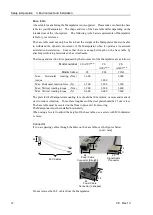
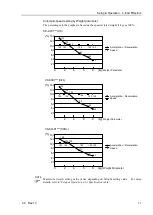
The acceptable weight capacity (end effector and work piece) for C8 series Manipulators is
as follows:
Rated
Maximum
3 kg
8 kg
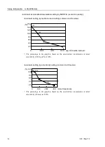
Change the setting of the Weight parameter according to the load.
After changing the Weight parameter setting, the maximum acceleration/deceleration and
speed of the robot system corresponding to the load is set automatically.
Setting method of Weight parameters
EPSON
RC+
Select [Tools]-[Robot Manager]-[Weight] panel and set the value in [Weight:].
You may also execute the Weight command from [Command Window].
Содержание C8 Series
Страница 1: ...Rev 13 EM208R4413F 6 Axis Robots C8 series MANIPULATOR MANUAL ...
Страница 2: ...Manipulator manual C8 series Rev 13 ...
Страница 8: ...vi C8 Rev 13 ...
Страница 14: ...Table of Contents xii C8 Rev 13 ...
Страница 16: ......
Страница 31: ...Setup Operation 2 Specifications C8 Rev 13 17 2 4 Outer Dimensions Unit mm 2 4 1 C8 A701 C8 ...
Страница 32: ...Setup Operation 2 Specifications 18 C8 Rev 13 2 4 2 C8 A901 C8L ...
Страница 33: ...Setup Operation 2 Specifications C8 Rev 13 19 2 4 3 C8 A1401 C8XL ...
Страница 49: ...Setup Operation 3 Environment and Installation C8 Rev 13 35 C8 A901 C8L ...
Страница 97: ...Maintenance This volume contains maintenance procedures with safety precautions for C8 series Manipulators ...
Страница 98: ......
Страница 183: ...Maintenance 4 Cable Unit C8 Rev 13 169 4 2 Connector Pin Assignment 4 2 1 Signal Cable ...
Страница 184: ...Maintenance 4 Cable Unit 170 C8 Rev 13 ...
Страница 185: ...Maintenance 4 Cable Unit C8 Rev 13 171 ...
Страница 186: ...Maintenance 4 Cable Unit 172 C8 Rev 13 4 2 2 Power Cable C8 A701 C8 C8 A901 C8L ...
Страница 187: ...Maintenance 4 Cable Unit C8 Rev 13 173 C8 A1401 C8XL ...
Страница 188: ...Maintenance 4 Cable Unit 174 C8 Rev 13 C8 A701 C8 C8 A901 C8L C8 A1401 C8XL ...

