
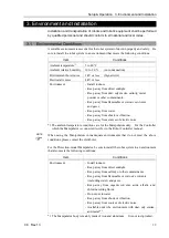


Setup & Operation 3. Environment and Installation
38
C8 Rev.13
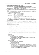
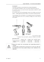
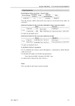
Base table
A base table for anchoring the Manipulator is not supplied. Please make or obtain the base
table for your Manipulator. The shape and size of the base table differ depending on the
intended use of the robot system. The following is the basic requirements of Manipulator
table for your reference.
The base table must not only be able to bear the weight of the Manipulator but also be able
to withstand the dynamic movement of the Manipulator when it operates at maximum
acceleration/deceleration. Ensure that there is enough strength on the base table by
attaching reinforcing materials such as crossbeams.
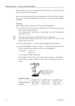
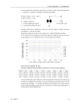
The torque and reaction force produced by the movement of the Manipulator are as follows:
Model number
C8-A701***
C8-
A901***
C8-
A1401***
Model name
C8
C8L
C8XL
Max. Horizontal rotating
torque
(N·m)
1,600
1,800
2,600
Max. Horizontal reaction force
(N)
1,200
1,300
1,300
Max. Vertical rotating torque
(N·m)
1,900
2,200
3,400
Max. Vertical rotating torque
(N)
6,600
6,000
7,800
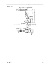
The plate for the Manipulator mounting face should be 30 mm thick or more and made of
steel to reduce vibration. The surface roughness of the steel plate should be 25
μ
m or less.
The base table must be secured on the floor to prevent it from moving.
The Manipulator must be installed horizontally.
When using a leveler to adjust the height of the base table, use a screw with M16 diameter
or more.
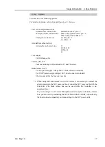
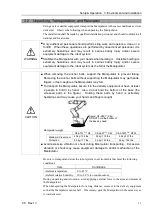
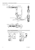
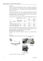
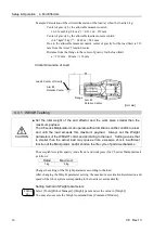
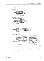
Connector
If you are passing cables through the holes on the base table, see the figures below.
[unit : mm]
66
49
11
44
54
35
82
Power Cable
Connector (Straight)
Signal Cable
Connector
M/C Cables
86
Power Cable
Connector (L-shaped)
85
35
80
Do not remove the M/C cables from the Manipulator.
Содержание C8 Series
Страница 1: ...Rev 13 EM208R4413F 6 Axis Robots C8 series MANIPULATOR MANUAL ...
Страница 2: ...Manipulator manual C8 series Rev 13 ...
Страница 8: ...vi C8 Rev 13 ...
Страница 14: ...Table of Contents xii C8 Rev 13 ...
Страница 16: ......
Страница 31: ...Setup Operation 2 Specifications C8 Rev 13 17 2 4 Outer Dimensions Unit mm 2 4 1 C8 A701 C8 ...
Страница 32: ...Setup Operation 2 Specifications 18 C8 Rev 13 2 4 2 C8 A901 C8L ...
Страница 33: ...Setup Operation 2 Specifications C8 Rev 13 19 2 4 3 C8 A1401 C8XL ...
Страница 49: ...Setup Operation 3 Environment and Installation C8 Rev 13 35 C8 A901 C8L ...
Страница 97: ...Maintenance This volume contains maintenance procedures with safety precautions for C8 series Manipulators ...
Страница 98: ......
Страница 183: ...Maintenance 4 Cable Unit C8 Rev 13 169 4 2 Connector Pin Assignment 4 2 1 Signal Cable ...
Страница 184: ...Maintenance 4 Cable Unit 170 C8 Rev 13 ...
Страница 185: ...Maintenance 4 Cable Unit C8 Rev 13 171 ...
Страница 186: ...Maintenance 4 Cable Unit 172 C8 Rev 13 4 2 2 Power Cable C8 A701 C8 C8 A901 C8L ...
Страница 187: ...Maintenance 4 Cable Unit C8 Rev 13 173 C8 A1401 C8XL ...
Страница 188: ...Maintenance 4 Cable Unit 174 C8 Rev 13 C8 A701 C8 C8 A901 C8L C8 A1401 C8XL ...


