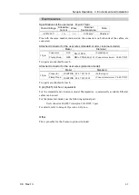
Setup & Operation 4. End Effectors
46
C8 Rev.13
4. End Effectors
4.1 Attaching an End Effector
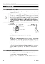
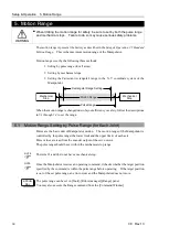
Create an end effector for your Manipulator. Flange dimensions of the wrist attached to
the end of Arm #6 is as below.
CAUTION
■
If you use an end effector equipped with a gripper or chuck, connect wires and/or
pneumatic tubes properly so that the gripper does not release the work piece
when the power to the robot system is turned OFF. Improper connection of the
wires and/or pneumatic tubes may damage the robot system and/or work piece
as the work piece is released when the Emergency Stop switch is pressed.
I/O outputs are configured at the factory so that they are automatically shut off (0)
by power disconnection, the Emergency Stop switch, or the safety features of the
robot system.
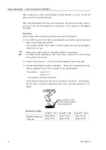
Wrist Flange
Arm #6
Attach an end effector to the end of the Arm #6 using the M5 bolts.
Layouts
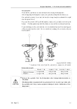
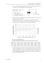
When you operate the Manipulator with an end effector, the end effector may interfere with
the Manipulator body depending on the outer diameter of the end effector, the size of the
work piece, or the position of the arms. When designing your system layout, pay close
attention to the interference area of the end effector.
Compatibility with ISO flange:
To install the end effector whose mounting dimensions are designed for the ISO flange, we
provide the optional C8 ISO flange (J6). For details, refer to
Setup & Operation: 6.
Options
.
4.2 Attaching Camera and Air Valves
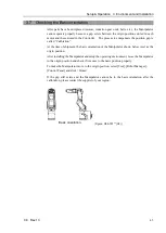
Decks are equipped to Arms #3 and #5 to enable the easy installation of air valve.
To mount the camera, the camera plate unit is necessary.
We provide the optional Camera Plate Unit. For details, refer to
Setup & Operation: 6.
Options
.
Содержание C8 Series
Страница 1: ...Rev 13 EM208R4413F 6 Axis Robots C8 series MANIPULATOR MANUAL ...
Страница 2: ...Manipulator manual C8 series Rev 13 ...
Страница 8: ...vi C8 Rev 13 ...
Страница 14: ...Table of Contents xii C8 Rev 13 ...
Страница 16: ......
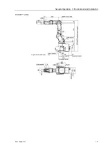
Страница 31: ...Setup Operation 2 Specifications C8 Rev 13 17 2 4 Outer Dimensions Unit mm 2 4 1 C8 A701 C8 ...
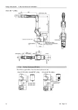
Страница 32: ...Setup Operation 2 Specifications 18 C8 Rev 13 2 4 2 C8 A901 C8L ...
Страница 33: ...Setup Operation 2 Specifications C8 Rev 13 19 2 4 3 C8 A1401 C8XL ...
Страница 49: ...Setup Operation 3 Environment and Installation C8 Rev 13 35 C8 A901 C8L ...
Страница 97: ...Maintenance This volume contains maintenance procedures with safety precautions for C8 series Manipulators ...
Страница 98: ......
Страница 183: ...Maintenance 4 Cable Unit C8 Rev 13 169 4 2 Connector Pin Assignment 4 2 1 Signal Cable ...
Страница 184: ...Maintenance 4 Cable Unit 170 C8 Rev 13 ...
Страница 185: ...Maintenance 4 Cable Unit C8 Rev 13 171 ...
Страница 186: ...Maintenance 4 Cable Unit 172 C8 Rev 13 4 2 2 Power Cable C8 A701 C8 C8 A901 C8L ...
Страница 187: ...Maintenance 4 Cable Unit C8 Rev 13 173 C8 A1401 C8XL ...
Страница 188: ...Maintenance 4 Cable Unit 174 C8 Rev 13 C8 A701 C8 C8 A901 C8L C8 A1401 C8XL ...

