


Setup & Operation 2. Specifications
24
C8 Rev.13
Item
Specification
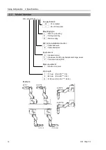
Model Number
C8-A701***
C8-A901***
C8-A1401***
Model Name
C8
C8L
C8XL
Allowable moment of
inertia (GD2/4)
*4
Joint #4
0.47 kg·m
2
Joint #5
0.47 kg·m
2
Joint #6
0.15 kg·m
2
Installed wire for customer use
15 wires (D-sub)
8 pin (RJ45) Cat 5e or equivalent
6 pin (for Force Sensor)
Installed pneumatic tube for customer use
*5
ø6 mm pneumatic tubes (2 tubes),
Allowable pressure: 0.59 MPa (6 kgf/cm
2
) (86 psi)
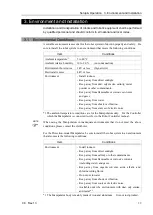
Environmental
requirements
*6
Ambient
Temperature
5 to 40
°
C
Ambient relative
humidity
10 to 80 % (no condensation)
Vibration
4.9 m
⋅
s
2
(0.5 G) or less
Noise level
*7
LAeq = 70 dB (A) or under
Environment
Standard
Cleanroom model & ESD
*8
Protection model (IP67)
*9
Applicable Controller
RC700-A, RC700DU-A
Default values
(Max. setting values)
SPEED
3 (100)
ACCEL
*10
5, 5 (120, 120)
SPEEDS
50 (2000)
ACCELS
*11
200 (35000)
120 (25000)
FINE
10000, 10000, 10000, 10000, 10000, 10000
(130000, 130000, 130000, 130000, 130000, 130000)
WEIGHT
3 (8)
INERTIA
0.03 (0.15)
Safety standard
CE Marking:
EMC Directive, Machinery Directive
KC Marking / KCs Marking
UL standards (In case of UL specification):
UL1740
ANSI/RIA R15.06
NFPA 79
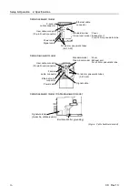
*1: Mounting types other than “Table Top mounting”, “Ceiling mounting”, and “Wall mounting” are out of
specification.
*2: In case of PTP control
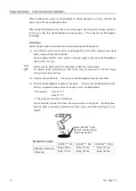
*3: Do not apply the load exceeding the maximum payload.
*4: If the center of gravity is at the center of each arm. If the center of gravity is not at the center of each arm,
set the eccentric quantity using INERTIA command.
*5: For details of the installed pneumatic tube for customer use, refer to the
Setup & Operation 3.6 User Wires
and Pneumatic Tubes
.
*6: For details of the environmental requirements, refer to the
Setup & Operation 3.1 Environmental Conditions
.
Содержание C8 Series
Страница 1: ...Rev 13 EM208R4413F 6 Axis Robots C8 series MANIPULATOR MANUAL ...
Страница 2: ...Manipulator manual C8 series Rev 13 ...
Страница 8: ...vi C8 Rev 13 ...
Страница 14: ...Table of Contents xii C8 Rev 13 ...
Страница 16: ......
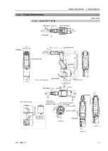
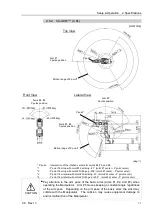
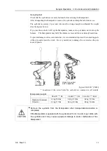
Страница 31: ...Setup Operation 2 Specifications C8 Rev 13 17 2 4 Outer Dimensions Unit mm 2 4 1 C8 A701 C8 ...
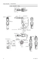
Страница 32: ...Setup Operation 2 Specifications 18 C8 Rev 13 2 4 2 C8 A901 C8L ...
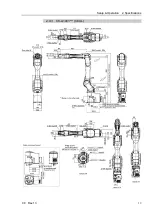
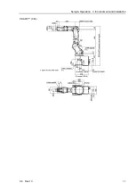
Страница 33: ...Setup Operation 2 Specifications C8 Rev 13 19 2 4 3 C8 A1401 C8XL ...
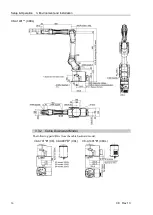
Страница 49: ...Setup Operation 3 Environment and Installation C8 Rev 13 35 C8 A901 C8L ...
Страница 97: ...Maintenance This volume contains maintenance procedures with safety precautions for C8 series Manipulators ...
Страница 98: ......
Страница 183: ...Maintenance 4 Cable Unit C8 Rev 13 169 4 2 Connector Pin Assignment 4 2 1 Signal Cable ...
Страница 184: ...Maintenance 4 Cable Unit 170 C8 Rev 13 ...
Страница 185: ...Maintenance 4 Cable Unit C8 Rev 13 171 ...
Страница 186: ...Maintenance 4 Cable Unit 172 C8 Rev 13 4 2 2 Power Cable C8 A701 C8 C8 A901 C8L ...
Страница 187: ...Maintenance 4 Cable Unit C8 Rev 13 173 C8 A1401 C8XL ...
Страница 188: ...Maintenance 4 Cable Unit 174 C8 Rev 13 C8 A701 C8 C8 A901 C8L C8 A1401 C8XL ...