Owners Manual Ecosaire
®
EN Series Precision Air Conditioner
Ecosaire
®
July 2009 17
Data subject to change without notice.
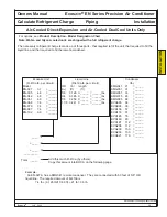
minimum 12 in.
(30 cm)
Vegetation must be
kept short.
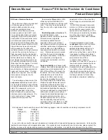
Important! - Inspect your unit immediately for shipping damage.
Claims for shipping damage must be made with the shipping
company.
Notify the carrier immediately if shipping damage is suspected.
If internal damage is suspected, indicate “contingent on internal inspection”
when signing for the shipment. Keep copies of all documents, including
photographs of any damage.
For units with a remote heat exchanger, select a suitable location for the
outdoor unit, where it will not be subject to damage. Outdoor condensers
(with Ecosaire unit of Cooling Type = A) must have no more than 100 ft.
(30 m) of tube (one way) connecting to the Ecosaire unit. Areas subject to
heavy snow and ice accumulation should be avoided. Areas subject to
public access should be avoided. Locate outdoor units in an area of clean
air away from steam, hot air, or fume exhausts.
Units installed on roofs should be mounted on steel supports in accordance with local codes. A concrete pad is
sufficient for ground installations.
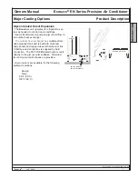
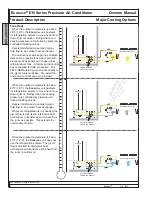
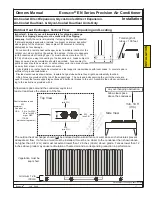
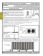
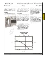
Provide clearances as shown below. Insulate hot-gas tubes where they might be accidentally touched.
Lifting holes are provided at the top of the support legs. The nuts and bolts securing the unit to the crate are
used to mount the lower support leg sections and horizontal braces to the unit. Assemble the outdoor unit accord-
ing to the instructions provided with it.
The outdoor heat exchanger should
not
be enclosed within a solid fence or wall, since such structures prevent
adequate air flow. If a fence or wall must be installed, it must be no closer to the condenser than shown above,
no higher than 6 ft (2 m) and must not extend lower than 12 inches (30 cm) above grade. Fences lower than 12
inches above grade may cause recirculation of heated air and a corresponding reduction in performance.
W
min. 10 ft
(3 m)
any overhanging obstruction
Top View
Allow clear space around the condenser equal to at
least at least twice the diameter of the fan.
Allow clear space
above the condenser.
Side View
2W
(min 3ft.)
2W
(min 3ft.)
2W
(min 3ft.)
Control enclosure end
2W
minimum:
Canada 1m
USA
36 in. for 230V
42 in. for 460V
or per NEC
110-26,
whichever is greater)
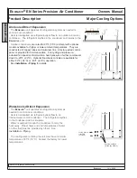
Outdoor Heat Exchanger, Vertical Flow Unpacking and Locating
Air-Cooled Direct Expansion, Glycol-Cooled Direct Expansion,
Installation
Air-Cooled DualCool, & Glycol-Cooled DualCool Units Only
Total length of
tubes
≤
100 feet.
INST
ALLA
TION
EXAMPLE
Appearance, location, and
quantity of component
s
may vary
.
Содержание EN Series
Страница 1: ......
Страница 103: ...OEM User manual ...
Страница 104: ......
Страница 106: ......
Страница 108: ......
Страница 110: ......
Страница 115: ...OEM CAREL code 030221791 rel 2 1 21 09 07 7 KUE 4 L H A1 A2 S2 S1 V3 V1 P S V X X1 Y Y1 KUE CC ...
Страница 123: ...OEM CAREL code 030221791 rel 2 1 21 09 07 15 4 2 Single phase wiring diagram INTERNAL TAM CP2 ...
Страница 124: ...OEM CAREL code 030221791 rel 2 1 21 09 07 16 4 3 Single phase wiring diagram INTERNAL TAM with contactor CP4 ...
Страница 125: ...OEM CAREL code 030221791 rel 2 1 21 09 07 17 4 4 Single phase wiring diagram EXTERNAL TAM with contactor CP3 ...
Страница 126: ...OEM CAREL code 030221791 rel 2 1 21 09 07 18 4 5 Three phase wiring diagram EXTERNAL TAM with contactor CP3 ...
Страница 127: ...OEM CAREL code 030221791 rel 2 1 21 09 07 19 4 6 Three phase wiring diagram INTERNAL TAM with contactor CP4 ...
Страница 141: ......


