OEM
CAREL code +030221791 - rel. 2.1 – 21/09/07
25
6.2
Maintenance of the other components in the water circuit
IMPORTANT WARNINGS:
•
when cleaning the plastic components do not use detergents or solvents;
•
scale can removed using a solution of 20% acetic acid and then rinsing with water.
The steam humidifier has just one part that requires periodical replacement:
the steam production cylinder.
This operation is necessary when the lime scale deposits that form inside the cylinder prevent the sufficient passage of current. This
situation is displayed on the controller by an alarm signal. The frequency of this operation depends on the supply water: the higher
the content of salts or impurities, the more frequently the cylinder will need replacing.
no description
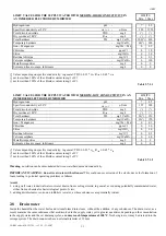
Order code
1
Load-bearing frame
2
Cylinder locking strap
18C499A006
3
Supply tank + conductivity meter
13C119A003
4
Overflow pipe
5
Cylinder fill hose
6
Tank fill hose
UEKT00000*
7
Fill solenoid valve
KITVC000**
8
Supply/drain assembly
13C499A030
9
Gasket
10
90° drain connector
11
Straight drain connector (supplied)
KITRACC000
12
Drain solenoid valve
13C499A030
Table 5.2.1
* for the complete codes see Table 5.4.1.1 and 5.4.3.1 “ SPARE PARTS”
•
Fill solenoid valve
(Fig. 5.2.1 , part no. 7, 5)
After having disconnected the cables and the pipe, remove the solenoid valve
and check the condition of the inlet filter; clean if necessary using water and a
soft brush.
•
Supply and drain manifold
(Fig. 5.2.1, part no. 8, 2)
Check that there are no solid residues in the cylinder attachment, remove any
impurities.
Check that the seal (O-ring) not is damaged or cracked; if necessary, replace
it.
•
Drain solenoid valve / drain pump
(Fig. 5.2.1 , part no. 12, 4)
Disconnect the power supply, remove the coil, unscrew the fastening screws
and remove the valve body; remove any impurities and rinse.
•
Supply tank + conductivity meter
(Fig. 5.2.1, part no. 3, 6)
Check that there are no obstructions or solid particles and that the electrodes
for measuring the conductivity are clean, remove any impurities and rinse.
•
Supply, fill, overflow pipes
(Fig. 5.2.1, part no. 4, 5, 6 – 8, 9, 10, 11)
Check that these are free and do not contain impurities; remove any
impurities and rinse.
Fig. 5.2.1
Содержание EN Series
Страница 1: ......
Страница 103: ...OEM User manual ...
Страница 104: ......
Страница 106: ......
Страница 108: ......
Страница 110: ......
Страница 115: ...OEM CAREL code 030221791 rel 2 1 21 09 07 7 KUE 4 L H A1 A2 S2 S1 V3 V1 P S V X X1 Y Y1 KUE CC ...
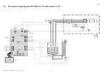
Страница 123: ...OEM CAREL code 030221791 rel 2 1 21 09 07 15 4 2 Single phase wiring diagram INTERNAL TAM CP2 ...
Страница 124: ...OEM CAREL code 030221791 rel 2 1 21 09 07 16 4 3 Single phase wiring diagram INTERNAL TAM with contactor CP4 ...
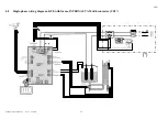
Страница 125: ...OEM CAREL code 030221791 rel 2 1 21 09 07 17 4 4 Single phase wiring diagram EXTERNAL TAM with contactor CP3 ...
Страница 126: ...OEM CAREL code 030221791 rel 2 1 21 09 07 18 4 5 Three phase wiring diagram EXTERNAL TAM with contactor CP3 ...
Страница 127: ...OEM CAREL code 030221791 rel 2 1 21 09 07 19 4 6 Three phase wiring diagram INTERNAL TAM with contactor CP4 ...
Страница 141: ......

