Ecosaire
®
EN Series Precision Air Conditioner Owners Manual
38
Ecosaire
®
July 2009
Data subject to change without notice.
J
Installation Wiring Power
IMPORTANT!
Before working on this or any
electrical equipment, disconnect
all electrical power. Failure to
do so may result in serious per-
sonal injury or death due to
accidental electrical shock.
The branch-circuit conductors
should be brought through the unit
cabinet to the high-voltage terminal
strip or factory-mounted disconnect
switch.
Wiring for the unit and remote
heat exchanger (if any) should
comply with applicable codes.
Important!
Always cover the electrical
components with plastic sheet
before drilling or sawing the
electrical enclosure. Do not
allow metal chips to fall into the
enclosure.
Important!
Use only copper conductors to
connect the unit. The power
input lugs are not sized for use
with other conductors. THE USE
OF OTHER THAN COPPER CON-
DUCTORS WILL VOID THE
EQUIPMENT WARRANTY. For
units with factory-supplied dis-
connects, follow instructions
inside the disconnect.
Important!
Ground the unit using the
grounding lug provided.
Important!
For
••
Air-Cooled Direct Expansion,
••
Glycol-Cooled Direct-
Expansion,
••
Air-Cooled DualCool,
••
Glycol-Cooled DualCool, and
••
FreeCool units
refer to the remote heat-
exchanger manual.
Wire the remote heat
exchanger according to the
wiring diagram provided with it.
Insure that the fan motors turn
in the correct direction.
Use properly sized wire
Refer to the unit nameplate for
electrical ratings. Size wires
according to applicable codes, with
allowance for voltage drops. Unit
terminal voltage should be nominal
±10% under all conditions, includ-
ing compressor starting.
Insure phase rotation
All the motors in the unit are con-
nected for the same phase rota-
tion. Be sure the phase rotation is
correct before completing the
installation.
Do not move any
factory-installed wires.
NOTE: The blower running direc-
tion can be used to test phase
rotation.
Insure phase voltage
The
Ecosaire
® unit complies with
NEMA MG-1 and other standards
for applied voltage. The applied
voltage should be within ±10% of
the nominal voltage shown on the
nameplate. See ANSI C84.1.
Phase voltages should be bal-
anced within 2%.
208V units
A minimum of 187V at the com-
pressor terminals is required for
compressor starting (see NEMA
MG-1). Allow for voltage drop
under inrush current conditions.
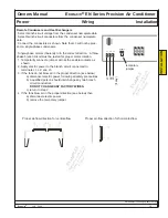
Connect input power as indicated.
Use copper wire only. Torque all connectors per NEC 110-14 or relevant code.
Position of power lugs may vary.
Some
Ecosaire
®
units may have optional
voltage monitors that prevent operation in the
event the branch circuit has voltage that is too
high, too low, has lost a phase, or has reversed
phase rotation. If the green LED
is not lit when power is applied to the unit, con-
firm that the applied voltage is within ±10% of
the nameplate voltage (NEMA MG-1), that all
three phases are present, and that the phase
rotation is correct.
INST
ALLA
TION
EXAMPLE
Appearance, location, and
quantity of component
s
may vary
.
Содержание EN Series
Страница 1: ......
Страница 103: ...OEM User manual ...
Страница 104: ......
Страница 106: ......
Страница 108: ......
Страница 110: ......
Страница 115: ...OEM CAREL code 030221791 rel 2 1 21 09 07 7 KUE 4 L H A1 A2 S2 S1 V3 V1 P S V X X1 Y Y1 KUE CC ...
Страница 123: ...OEM CAREL code 030221791 rel 2 1 21 09 07 15 4 2 Single phase wiring diagram INTERNAL TAM CP2 ...
Страница 124: ...OEM CAREL code 030221791 rel 2 1 21 09 07 16 4 3 Single phase wiring diagram INTERNAL TAM with contactor CP4 ...
Страница 125: ...OEM CAREL code 030221791 rel 2 1 21 09 07 17 4 4 Single phase wiring diagram EXTERNAL TAM with contactor CP3 ...
Страница 126: ...OEM CAREL code 030221791 rel 2 1 21 09 07 18 4 5 Three phase wiring diagram EXTERNAL TAM with contactor CP3 ...
Страница 127: ...OEM CAREL code 030221791 rel 2 1 21 09 07 19 4 6 Three phase wiring diagram INTERNAL TAM with contactor CP4 ...
Страница 141: ......

