Owners Manual Ecosaire
®
EN Series Precision Air Conditioner
Ecosaire
®
July 2009
65
Data subject to change without notice.
Startup
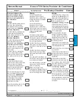
Remote heat exchanger
installed properly?
(See HX manu-
al.)
Wire connections checked for
tightness?
(See
Installation -
Wiring - Power
.)
Pre-Startup check list complete?
(
See
Startup - Pre-Startup
Checklists
.)
Blower rotation on 3-phase units
correct?
(See
Installation - Wiring
- Power
.)
Airflow and blower speed adjust-
ed?
(See
Installation - Air
Distribution - Adjust Airflow
.)
Airflow . . . . . . . . . . . . . . .cfm
Refrigerant charge OK?
No alarms displayed?
Set points at design conditions?
Proper air distribution provided?
(See
Installation - Air
Distribution
.)
Vapor retardant installed prop-
erly?
(See
Building - Moisture
Migration
.)
Adequate service access pro-
vided?
(See
Installation -
Unpacking & Locating
.)
Unit level?
Main disconnect switch
installed?
(See
Installation -
Wiring - Power
.)
Optional fire alarm tested?
Water detectors tested?
Condensate drain connected,
P-trap installed, filled and
tested?
Condensate pump (if any)
operating?
Loss-of-airflow alarm tested?
Dirty filter alarm tested?
Humidifier jumpers correct?
Humidifier connectors tight?
All sensor readings true?
Date and time set?
All alarms cleared?
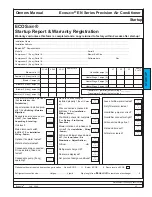
ECOSaire®
Startup Report & Warranty Registration
Warranty void unless this form is completed and a copy returned to factory within 2 weeks after start-up!
Installation Name..................................................................................................................................................................................
Installation Address ..............................................................................................................................................................................
Ecosaire
®
Representative.................................................................................................................................................................
Model # ......................................................................................................................Serial # ..............................................................
Compressor 1 (if any) Serial #...................................................................................Blower Belt Size................................................
Compressor 2 (if any) Serial #...................................................................................Software date . . . . . . . . . . . . . Rev. . . . . . . . .
Compressor 3 (if any) Serial #...................................................................................
Compressor 4 (if any) Serial #...................................................................................
your
initials
your
initials
your
initials
your
initials
your
initials
your
initials
your
initials
your
initials
your
initials
your
initials
your
initials
your
initials
your
initials
your
initials
your
initials
your
initials
your
initials
your
initials
your
initials
your
initials
your
initials
your
initials
your
initials
your
initials
your
initials
Blower volts (V)
L1-L2
L2-L3
L3-L1
NAMEPLATE
Remote HX (if any) volts (V)
Blower 1 amps (A)
Blower 3 (if any) amps (A)
Blower 2 (if any) amps (A)
Remote HX (if any) amps (A)
Humidifier amps (A)
Transformer 1 (smaller) output voltage ________
Transformer 2 (larger) output voltage ________
Heater Stage 1 amps (A)
L1
L2
L3
NAME
PLATE
Heater Stage 2 amps (A)
Heater Stage 3 amps (A)
Optional outdoor air-cooled heat exchanger location
Above ECOS . . . . ft Below ECOS . . . . ft
Same level as ECOS
Refrigerant connection size.....................Hot gas ...................Liquid Pipe length from
Ecosaire
®
to remote heat exchanger . . . . . . ft
ST
ARTUP
Содержание EN Series
Страница 1: ......
Страница 103: ...OEM User manual ...
Страница 104: ......
Страница 106: ......
Страница 108: ......
Страница 110: ......
Страница 115: ...OEM CAREL code 030221791 rel 2 1 21 09 07 7 KUE 4 L H A1 A2 S2 S1 V3 V1 P S V X X1 Y Y1 KUE CC ...
Страница 123: ...OEM CAREL code 030221791 rel 2 1 21 09 07 15 4 2 Single phase wiring diagram INTERNAL TAM CP2 ...
Страница 124: ...OEM CAREL code 030221791 rel 2 1 21 09 07 16 4 3 Single phase wiring diagram INTERNAL TAM with contactor CP4 ...
Страница 125: ...OEM CAREL code 030221791 rel 2 1 21 09 07 17 4 4 Single phase wiring diagram EXTERNAL TAM with contactor CP3 ...
Страница 126: ...OEM CAREL code 030221791 rel 2 1 21 09 07 18 4 5 Three phase wiring diagram EXTERNAL TAM with contactor CP3 ...
Страница 127: ...OEM CAREL code 030221791 rel 2 1 21 09 07 19 4 6 Three phase wiring diagram INTERNAL TAM with contactor CP4 ...
Страница 141: ......


