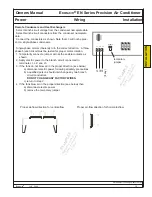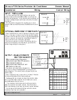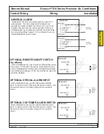
Ecos
aire
®
EN Series Precision Air Conditioner Owners Manual
Installation Wiring Control Wiring
40
Ecos
aire
®
July 2007
Data subject to change without notice.
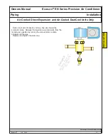
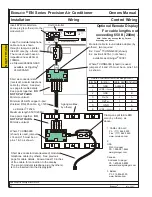
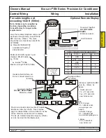
Short six-conductor data
(reversed) modular telephone
cable (by others). See previ-
ous page for cable details.
BL
UE/
W
HI
T
E
W
H
IT
E/
BL
UE
SHI
E
LD
ORA
N
GE
/W
HI
T
E
W
H
IT
E/
O
R
ANG
E
G
R
EEN/
W
HI
TE
WH
IT
E
/G
R
E
E
N
B
LUE/
W
HI
T
E
W
H
IT
E/
BL
UE
SHI
E
LD
ORA
N
GE
/W
HI
T
E
W
H
IT
E
/ORA
N
GE
G
R
EEN/
W
HI
TE
W
H
IT
E
/G
R
EEN
J14
J1
5
6
5
4
3
2
1
0
J14
J15
6 5 4 3 2 1 0
J11
J12
Expansion Memory
J9
J10
C1
Rx
-/
T
x-
NO1
Rx
+
/T
x+
NO2
GND
NO
3
C1
Cable conductor-terminal assignment
terminal
function cable pair conductor
0
SHIELD
GND
1
A
1
+VRL
(~30Vdc)
2
B
1
GND
3
A
2
Rx/Tx-
4
B
2
Rx/Tx+
5
A
3
GND
6
B
3
+VRL
(~30Vdc)
Minimum 24 AWG copper 3-pair
shielded RS-485 cable, Z0 =120
Ω
ex: Belden3 7202A
Maximum length 650 ft (200m)
Optional Remote Display
Short six-conductor data (reversed) modular
telephone cable (by others). See previous
page for cable details. Allow at least 10 inches
of free cable for connection to the display.
The six-pin modular telephone plug (by others)
is to be inserted into the display jack.
Insert 6P6C modular tele-
phone plug (by others) into the
modular port.
Unit Controller
Modular cable to round cable adapter, (by
others), two required
Ex: Carel1 TCONN6J000 (shown)
Ex: Leviton 40276-I, (not shown)
available as Grainger2 5C381
Where TCONN6000 (shown) is used,
jumpers J14 and J15 must be on pins 1 & 3
as shown.
Where TCONN6000
(shown) is used, jumpers
J14 and J15 must be on
pins 1 & 3 as shown.
Keep pairs together.
DO
NOT SPLIT PAIRS.
Minimize untwist.
Keep pairs together.
DO
NOT SPLIT PAIRS.
Minimize untwist.
1. CAREL USA LLC
Ph: (717) 664-0500
Fax: (717) 664-0449
www.carelusa.com
2.
USA
W.W. Grainger
Ph: 1-888-361-8649
www.grainger.com
Canada
Acklands Grainger
Ph. 1-800-668-8989
www.acklandsgrainger.com
3. Belden
Ph. 314-854-8000
www.belden.com
Loop the modular telephone
cable once as shown
through clamp-on split fer-
rite EMI core (by others).
The cores should have an
impedance near 240
Ω
at
100MHz.
ex: Steward 28A0640-0A0
available as Digi-Key1
240-2065-ND
Clamp-on split ferrite EMI
core (by others), as
above.
3-gang wallbox,
by others)
INST
ALLA
TION
For cable lengths not
exceeding 650 ft (200m) -
Note: Cables may be supplied by Dectron,
depending on options.
Содержание EN Series
Страница 1: ......
Страница 103: ...OEM User manual ...
Страница 104: ......
Страница 106: ......
Страница 108: ......
Страница 110: ......
Страница 115: ...OEM CAREL code 030221791 rel 2 1 21 09 07 7 KUE 4 L H A1 A2 S2 S1 V3 V1 P S V X X1 Y Y1 KUE CC ...
Страница 123: ...OEM CAREL code 030221791 rel 2 1 21 09 07 15 4 2 Single phase wiring diagram INTERNAL TAM CP2 ...
Страница 124: ...OEM CAREL code 030221791 rel 2 1 21 09 07 16 4 3 Single phase wiring diagram INTERNAL TAM with contactor CP4 ...
Страница 125: ...OEM CAREL code 030221791 rel 2 1 21 09 07 17 4 4 Single phase wiring diagram EXTERNAL TAM with contactor CP3 ...
Страница 126: ...OEM CAREL code 030221791 rel 2 1 21 09 07 18 4 5 Three phase wiring diagram EXTERNAL TAM with contactor CP3 ...
Страница 127: ...OEM CAREL code 030221791 rel 2 1 21 09 07 19 4 6 Three phase wiring diagram INTERNAL TAM with contactor CP4 ...
Страница 141: ......


