Air-Cooled Direct-Expansion and Air-Cooled DualCool Units Only
Ecosaire
®
EN Series Precision Air Conditioner Owners Manual
32
Ecosaire
®
July 2009
Data subject to change without notice.
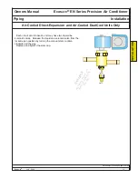
Installation Piping Refrigerant-Tube Joining
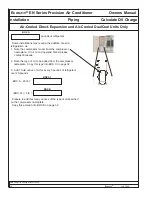
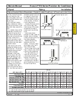
After eliminating all leaks, locate the refrigerant receiver in the remote condenser
unit. Open the receiver isolation valves (if any).
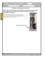
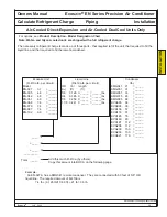
evacuation manifold
(by others)
hoses
(by others)
vacuum pump with
isolation valve
(by others)
refrigeration manifold
(by others)
refrigerant
and scale
(by others)
essential electronic
evacuation gauge
(by others)
liquid-line access
valve added
previously
(by others)
Open the compressor(s) rotalock valves to the access (middle) position. The
Ecosaire® unit, condenser, and tubes must be evacuated to a pressure below 500
microns of mercury as measured by an electronic vacuum gauge.
Compound gauges
as found on refrigeration manifolds are not adequate.
IMPORTANT!
Under no circumstances use the compressor as a vacuum pump or apply power to a compressor under
vacuum. Damage to the motor windings will result.
Connect a good set of refrigeration service gauges, an electronic micron-level vacuum gauge, and a vacuum pump
as shown below. Use core-removal adapters to remove the cores from Schraeder-type access valves.
To insure a correct vacuum reading, install the electronic vacuum gauge far away from the vacuum pump
or use a reliable vacuum valve to isolate the gauge and system from the pump while reading the vacuum.
Colder ambient temperatures require longer evacuation times. Allow enough time at low pressures to remove any
water from the tubes. The triple-evacuation method can be helpful.
After proper evacuation, close the vacuum pump valve and break the vacuum with vapor refrigerant until a positive
pressure is reached.
Close the compressor rotalock valves.
Continue adding the specified weight and type of refrigerant (by others), through the condenser
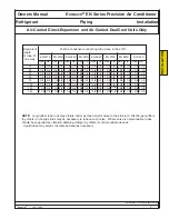
access valve, until the total amount shown in BOX A has been added.
Add the amount and type of oil shown in BOX B and BOX C.
Replace the access-valve cores and remove the adapters.
DO NOT put liquid refrigerant into the low-pressure access valve.
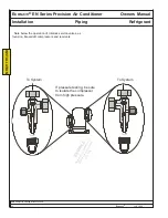
Open compressor
rotalock valves to access
position during evacuation.
INST
ALLA
TION
EXAMPLE
Appearance, location, and
quantity of component
s
may vary
.
BOX A
BOX B
BOX C
Содержание EN Series
Страница 1: ......
Страница 103: ...OEM User manual ...
Страница 104: ......
Страница 106: ......
Страница 108: ......
Страница 110: ......
Страница 115: ...OEM CAREL code 030221791 rel 2 1 21 09 07 7 KUE 4 L H A1 A2 S2 S1 V3 V1 P S V X X1 Y Y1 KUE CC ...
Страница 123: ...OEM CAREL code 030221791 rel 2 1 21 09 07 15 4 2 Single phase wiring diagram INTERNAL TAM CP2 ...
Страница 124: ...OEM CAREL code 030221791 rel 2 1 21 09 07 16 4 3 Single phase wiring diagram INTERNAL TAM with contactor CP4 ...
Страница 125: ...OEM CAREL code 030221791 rel 2 1 21 09 07 17 4 4 Single phase wiring diagram EXTERNAL TAM with contactor CP3 ...
Страница 126: ...OEM CAREL code 030221791 rel 2 1 21 09 07 18 4 5 Three phase wiring diagram EXTERNAL TAM with contactor CP3 ...
Страница 127: ...OEM CAREL code 030221791 rel 2 1 21 09 07 19 4 6 Three phase wiring diagram INTERNAL TAM with contactor CP4 ...
Страница 141: ......

