OPERATING
SECTION 4
Page 35
DRESSTA
OM515C520C99/1E
LOADER OPERATIONS
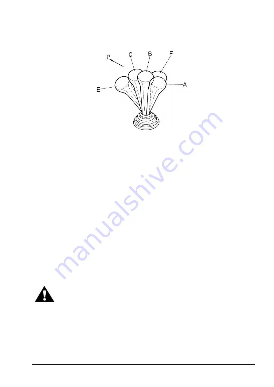
Fig. 4.29. Boom Control Lever Positions (Upgraded Version)
A. Raise
B. Hold
C. Lower
E. Bucket Rollback
F. Bucket Dump
P. Forward Direction of the Lever
In standard version the boom control is located to the far right of the operator's seat. It has four
positions: A, B, C, D (“raise", "hold", "lower", and "float").
In upgrade d version, a single lever controlling both the boom and the bucket movement is located
on the right of the operator’s seat. It has three positions for boom control: “raise", "hold", "lower",
and three positions for bucket control: “rollback", "dump" and "hold". The hold position is common
for both the bucket and the boom.
RAISE (A, Fig. 4.28, 4.29)
To raise the boom assembly, pull the lever back as far as it will go. A solenoid latch in the valve
locks the lever in detented position. The return to "HOLD" must be done manually or will be done
automatically when the boom reaches the preset stopping height of the automatic boom kick-out.
HOLD (B, Fig. 4.28, 4.29)
The control lever, when not in a detented position, will automatically return to "HOLD" when
released. The boom will remain stationary in this position.
LOWER (C, Fig. 4.28, 4.29)
Push the lever part way forward (in standard version) or all the way forward (in upgraded version) to
lower the boom. The lever will automatically return to "HOLD" when released.
WARNING! Do not leave the machine with a raised boom. The boom may drop
down even if the engine is shut down. (Refer to CHANGING THE HYDRAULIC
SYSTEM OIL, Section 5.14.2).
FLOAT (D, Fig. 4.28, FOR STANDARD VERSION)
The boom assembly can be lowered at any time by moving the lever to C “lower" or D “float"
position. Push the lever all the way forward for this position. This position is detented so the lever
must be pulled back manually to the "hold" position. Use the “float" position to follow the contour of
the ground when leveling or to lower the boom by gravity.
Содержание 515C
Страница 3: ...OM515C520C99 1E DRESSTA ...
Страница 5: ......
Страница 7: ......
Страница 10: ...SECTION 1 INTRODUCTION ...
Страница 11: ...INTRODUCTION SECTION 1 DRESSTA OM515C520C99 1E SECTION CONTENTS 1 1 Introduction 3 1 2 Serial Numbers 5 ...
Страница 12: ......
Страница 17: ...SECTION 2 SAFETY PRECAUTIONS ...
Страница 19: ......
Страница 37: ...SECTION 3 MACHINE TRANSPORT AND STORAGE ...
Страница 39: ......
Страница 49: ...SECTION 4 OPERATING ...
Страница 51: ......
Страница 55: ...SECTION 4 OPERATING Page 6 OM515C520C99 1E DRESSTA UNIVERSAL SYMBOLS FOR INSTRUMENTS AND CONTROLS ...
Страница 107: ...SECTION 5 MAINTENANCE ...
Страница 165: ...SECTION 6 SPECIFICATIONS ...
Страница 167: ......
Страница 181: ...SECTION 6 SPECIFICATIONS Page 16 OM515C520C99 1E DRESSTA WIRING DIAGRAMS ...
Страница 182: ...SPECIFICATIONS SECTION 6 Page 17 DRESSTA OM515C520C99 1E WIRING DIAGRAMS ...
Страница 187: ...SECTION 6 SPECIFICATIONS Page 22 OM515C520C99 1E DRESSTA WIRING DIAGRAMS ...
Страница 192: ...SPECIFICATIONS SECTION 6 Page 27 DRESSTA OM515C520C99 1E SPECIFICATIONS Fig 6 10A Overall Dimensions Wheel Loader 520C ...


