SECTION 5
MAINTENANCE
Page 6
OM515C520C99/1E
DRESSTA
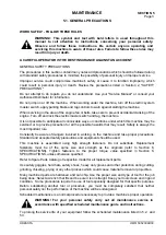
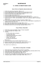
SCHEDULED MAINTENANCE GUIDE
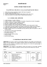
Every 2000 Hours of Operation or every year (per Engine Operation Manual)
1. Perform the service as specified in "Every 1000 hours of operation"
2. Change the brake fluid. Refer to 5.7.3.
3. Clean the cooling system and change coolant. Refer to 5.8.5, 5.8.6., 5.8.7.
4. Check the condition of the muffler. Refer to Engine Operation Manual.
5.2.1. GROUND LEVEL INSPECTION
1. Loader Equipment: condition, efficiency.
2. Radiator: condition, evidence of leakage and condition of the grill (rod or sand - if equipped).
3. Hydraulic components: condition, leakage, operation.
4. Drive train: condition, leakage, noise, clearance.
5. Wheels: condition of tires, tire mounting on wheel rims.
6. Engine compartment: fuel, air intake, exhaust, lubrication and cooling system for leaks.
7. Control panels: check the condition and operation of instruments, gauges and warning lights.
8. ROPS: the condition of ROPS cab, operator’s seat with seat belt, access openings.
No defects of ROPS structure are permissible that may adversely affect its protection in case of
machine rollover.
9. Visually check the screw joints, particularly:
•
Drive axle to frame mounting,
•
Driveshaft connecting,
•
Center articulation pivot mounting,
•
Wheel mounting,
•
Cab to frame mounting.
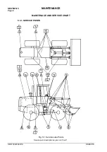
5.3. MAINTENACE AND SERVICE CHART
IMPORTANT:
The
points of service are individually explained in more details in the following text.
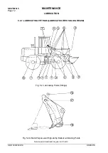
Always use clean lubricators and containers. Wipe the dirt from the fittings before fresh grease is
added. Use the hourmeter to determine service intervals. Do not use the warning lights to
determine the
service intervals.
IMPORTANT:
The
intervals of time between services are based on the average operating
conditions. In severe conditions of operation reduce the interval of time between the services.
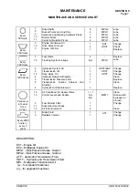
Chart 1.
Service
Interval
Ref.No
Point of Service
Service
Points
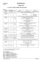
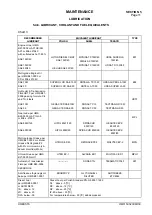
Lubricant
Service
Every
10 Hours
1
2
3
4
5
6
3
Ground Level Inspection
Brake Fluid Level
Radiator Coolant Level
Engine Crankcase Oil Level
Hydraulic Reservoir Oil Level
Transmission Oil Level
Fuel Tank
Water Separator
1
1
1
1
1
1
1
-
-
-
EO1
HDTF/EO2
HDTF
-
-
Perform
Check
Check
Check
Check
Check
Drain Water
and Sediment
Содержание 515C
Страница 3: ...OM515C520C99 1E DRESSTA ...
Страница 5: ......
Страница 7: ......
Страница 10: ...SECTION 1 INTRODUCTION ...
Страница 11: ...INTRODUCTION SECTION 1 DRESSTA OM515C520C99 1E SECTION CONTENTS 1 1 Introduction 3 1 2 Serial Numbers 5 ...
Страница 12: ......
Страница 17: ...SECTION 2 SAFETY PRECAUTIONS ...
Страница 19: ......
Страница 37: ...SECTION 3 MACHINE TRANSPORT AND STORAGE ...
Страница 39: ......
Страница 49: ...SECTION 4 OPERATING ...
Страница 51: ......
Страница 55: ...SECTION 4 OPERATING Page 6 OM515C520C99 1E DRESSTA UNIVERSAL SYMBOLS FOR INSTRUMENTS AND CONTROLS ...
Страница 107: ...SECTION 5 MAINTENANCE ...
Страница 165: ...SECTION 6 SPECIFICATIONS ...
Страница 167: ......
Страница 181: ...SECTION 6 SPECIFICATIONS Page 16 OM515C520C99 1E DRESSTA WIRING DIAGRAMS ...
Страница 182: ...SPECIFICATIONS SECTION 6 Page 17 DRESSTA OM515C520C99 1E WIRING DIAGRAMS ...
Страница 187: ...SECTION 6 SPECIFICATIONS Page 22 OM515C520C99 1E DRESSTA WIRING DIAGRAMS ...
Страница 192: ...SPECIFICATIONS SECTION 6 Page 27 DRESSTA OM515C520C99 1E SPECIFICATIONS Fig 6 10A Overall Dimensions Wheel Loader 520C ...


