MAINTENANCE
SECTION 5
Page 41
DRESSTA
OM515C520C99/1E
ENGINE
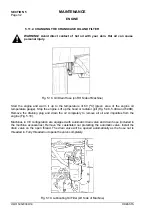
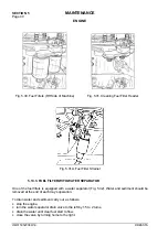
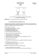
Fig. 5.32. Draining Fuel Filter Water Separator (RH Side of Machine)
(left - draining right - closing)
IMPORTANT:
Do not overtighten the valve not to damage valve thread.
5.13.4. VENTING THE FUEL SYSTEM (Fig. 5.33)
Controlled venting is provided at the injection pump through the fuel drain pipe. Small amounts of air
introduced by changing the filters or injection pump supply line will be vented automatically provided
the filters are changed in accordance with the instructions.
Manual venting will be required if:
a) the fuel filters are not filled prior to installation,
b) the injection pump is replaced,
c) the high presser fuel lines are replaced,
d) after machine’s prolonged standstill,
e) if the fuel tank has been emptied completely.
Vent the low pressure lines and fuel filters as follows:
1. Lift the hood (Fig. 5.48, 5.48A and 5.48B).
2. Open bleeder screw (1) on the filter header.
3. Operate hand lever (2) until the fuel flowing from the vent plug hole is free of air.
4. Tighten the bleeder screw to 8 [Nm].
Vent the injection pump as follows:
1. Bosch PES6A in-line injection pumps are equipped with automatic venting system.
Vent the high pressure lines as follows:
1. Loosen the high pressure line nut on one of the injectors.
2. Crank the engine till clean fuel appears.
NOTE:
While cranking keep away from the rotating engine parts.
3. Torque the high pressure line nut to 24 [Nm].
4. Start the engine and run it at low idle till the system is vented (smooth operation)
Содержание 515C
Страница 3: ...OM515C520C99 1E DRESSTA ...
Страница 5: ......
Страница 7: ......
Страница 10: ...SECTION 1 INTRODUCTION ...
Страница 11: ...INTRODUCTION SECTION 1 DRESSTA OM515C520C99 1E SECTION CONTENTS 1 1 Introduction 3 1 2 Serial Numbers 5 ...
Страница 12: ......
Страница 17: ...SECTION 2 SAFETY PRECAUTIONS ...
Страница 19: ......
Страница 37: ...SECTION 3 MACHINE TRANSPORT AND STORAGE ...
Страница 39: ......
Страница 49: ...SECTION 4 OPERATING ...
Страница 51: ......
Страница 55: ...SECTION 4 OPERATING Page 6 OM515C520C99 1E DRESSTA UNIVERSAL SYMBOLS FOR INSTRUMENTS AND CONTROLS ...
Страница 107: ...SECTION 5 MAINTENANCE ...
Страница 165: ...SECTION 6 SPECIFICATIONS ...
Страница 167: ......
Страница 181: ...SECTION 6 SPECIFICATIONS Page 16 OM515C520C99 1E DRESSTA WIRING DIAGRAMS ...
Страница 182: ...SPECIFICATIONS SECTION 6 Page 17 DRESSTA OM515C520C99 1E WIRING DIAGRAMS ...
Страница 187: ...SECTION 6 SPECIFICATIONS Page 22 OM515C520C99 1E DRESSTA WIRING DIAGRAMS ...
Страница 192: ...SPECIFICATIONS SECTION 6 Page 27 DRESSTA OM515C520C99 1E SPECIFICATIONS Fig 6 10A Overall Dimensions Wheel Loader 520C ...

