SECTION 4
OPERATING
Page 16
OM515C520C99/1E
DRESSTA
INSTRUMENTS AND CONTROLS
30. STEERING WHEEL HEIGHT ADJUSTMENT KNOB
The steering wheel operates the steering valve, which directs hydraulic fluid into the steering
cylinders. When the steering wheel is turned clockwise, the steering cylinders articulate the
machine so a right turn can be made. When the steering wheel is turned counterclockwise, the
machine is articulated so a left turn can be made. The machine continues as long as you turn the
steering wheel. When you stop turning the steering wheel, the machine will remain in the articulated
position it is in.
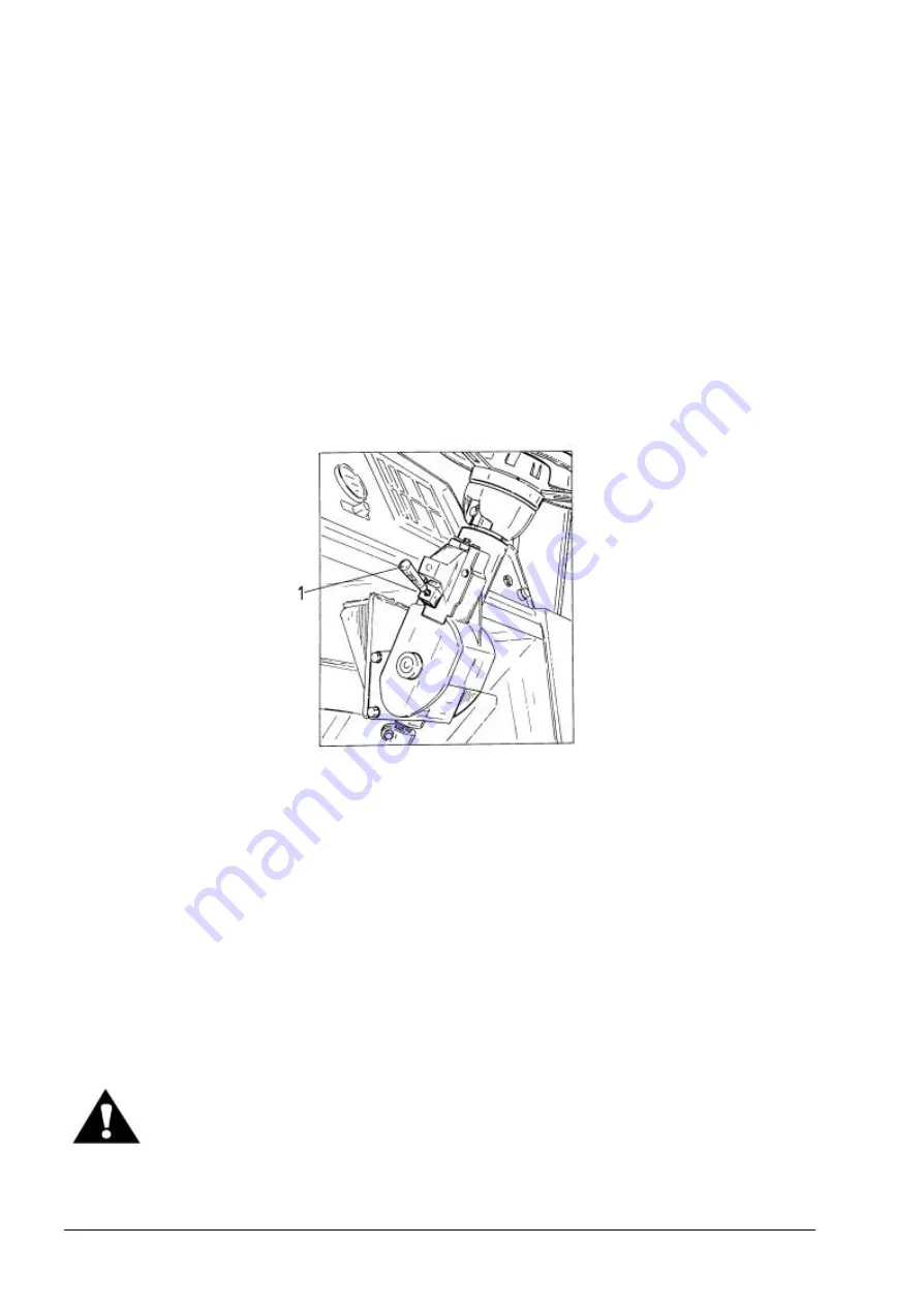
In the upgraded machine steering column height and its inclination can be adjusted (total
adjustment ranges up to 80 [mm] and 40 [
°
] respectively). Adjustment can be made after releasing
lever (1, Fig. 4.6). Pull the lever up to extend the steering column. Push it down to change the
inclination.
Fig. 4.6. Steering Column Adjustment (Upgraded Machine)
1. Lever
31. HORN BUTTON
Depress the button to sound the horn, release the button to stop.
32. BRAKE PEDAL
This pedal actuates the machine service brakes. Depress the pedal, gradually increasing pressure
until a desired braking action is achieved. The faster pressure is applied to the pedal, the stronger is
the braking action.
33. BRAKE AND TRANSMISSION DISCONNECT PEDAL
This pedal works in the same manner as the brake pedal except that it also relieves clutch pressure
in the transmission. When this pedal is depressed, no power can be transmitted through the
transmission and full engine power can be used to operate the machine hydraulics while braking.
WARNING! Do not press the transmission disconnect pedal when traveling fast
or going downhill because this shifts the transmission into neutral. Loss of
control or damage to the power train could result when the pedal is released
and transmission re-engages.
Содержание 515C
Страница 3: ...OM515C520C99 1E DRESSTA ...
Страница 5: ......
Страница 7: ......
Страница 10: ...SECTION 1 INTRODUCTION ...
Страница 11: ...INTRODUCTION SECTION 1 DRESSTA OM515C520C99 1E SECTION CONTENTS 1 1 Introduction 3 1 2 Serial Numbers 5 ...
Страница 12: ......
Страница 17: ...SECTION 2 SAFETY PRECAUTIONS ...
Страница 19: ......
Страница 37: ...SECTION 3 MACHINE TRANSPORT AND STORAGE ...
Страница 39: ......
Страница 49: ...SECTION 4 OPERATING ...
Страница 51: ......
Страница 55: ...SECTION 4 OPERATING Page 6 OM515C520C99 1E DRESSTA UNIVERSAL SYMBOLS FOR INSTRUMENTS AND CONTROLS ...
Страница 107: ...SECTION 5 MAINTENANCE ...
Страница 165: ...SECTION 6 SPECIFICATIONS ...
Страница 167: ......
Страница 181: ...SECTION 6 SPECIFICATIONS Page 16 OM515C520C99 1E DRESSTA WIRING DIAGRAMS ...
Страница 182: ...SPECIFICATIONS SECTION 6 Page 17 DRESSTA OM515C520C99 1E WIRING DIAGRAMS ...
Страница 187: ...SECTION 6 SPECIFICATIONS Page 22 OM515C520C99 1E DRESSTA WIRING DIAGRAMS ...
Страница 192: ...SPECIFICATIONS SECTION 6 Page 27 DRESSTA OM515C520C99 1E SPECIFICATIONS Fig 6 10A Overall Dimensions Wheel Loader 520C ...


