MAINTENANCE
SECTION 5
Page 33
DRESSTA
OM515C520C99/1E
ENGINE
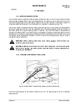
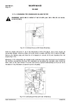
Clean the area around the filter header. Using a filter wrench, remove the oil filter (Fig. 5.19). Clean
the filter gasket surface of the filter header.
IMPORTANT:
The oil filter O-ring may stick to the filter header. Make sure the O-ring is removed.
Apply a thin coat of clean engine oil to the seal of the filter. Fill the new filter with clean engine oil.
IMPORTANT:
If the filter is not filled with engine oil, there will be a lack of lubrication during the
delay until the filters are pumped full of oil. This lack of lubrication is harmful to the engine.
Install the filter on the filter head.
IMPORTANT:
Do not overtighten the filter. This can warp the thread and damage the filter seal.
Check the condition and clean the drain plug thread and the gasket contact surface. Reinstall and
tighten the drain plug.
IMPORTANT:
Use high quality oil as specified in Chart 2 and 3.
Refill the engine with fresh and clean oil up to the required level. The total capacity of the engine
crankcase is 14 liters (Refer to Chart 2). The filter capacity is 2 liters. Check the oil level.
Start the engine and idle it for a few minutes. Inspect for oil leaks at the filters and drain plug. Then
stop the engine, wait for 15 minutes to allow the oil to drain and check the oil level. If necessary, add
oil to bring the oil level up to specified mark H on the oil dipstick.
5.11.3. CHECKING THE CONDITION AND TENSION OF BELTS
INSPECTION
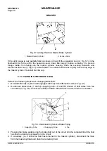
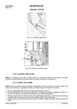
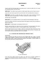
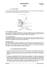
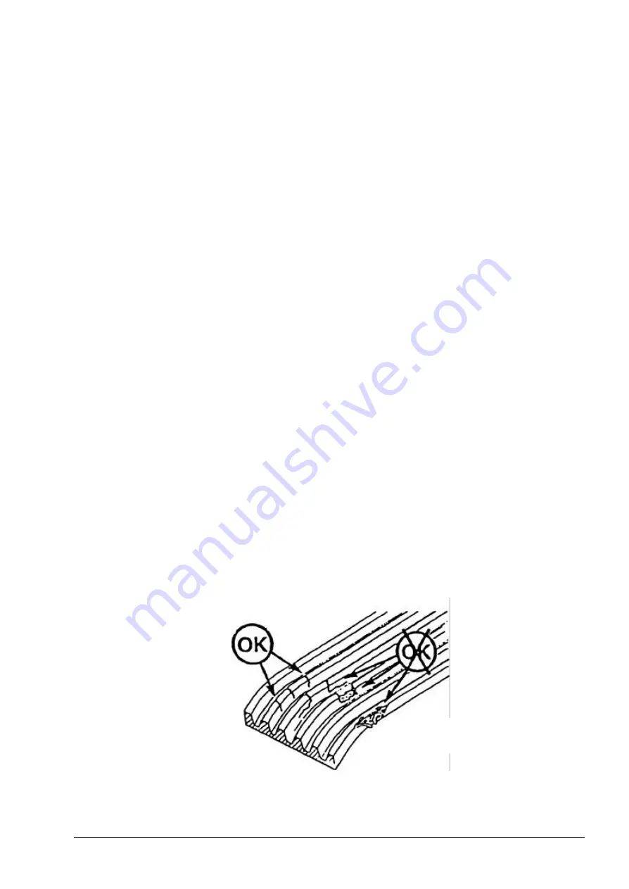
Inspect visually the drive belts every day (Fig. 5.20). Replace badly worn, greasy or severely
cracked belts immediately. Transverse (across the belt width) cracks are acceptable. Adjust the
belts that have shiny or glazed surface, which indicates belt slippage. Correctly installed and
tensioned belts will show even pulley and belt wear.
Fig. 5.20. Belt Inspection
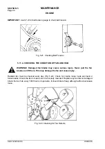
Check belt tension midway between the pulleys every 1000 hours of operation. Application of
a force of 270 to 580 [N] should cause deflection of a belt of 9.5 – 12.7 [mm] at the most.
Содержание 515C
Страница 3: ...OM515C520C99 1E DRESSTA ...
Страница 5: ......
Страница 7: ......
Страница 10: ...SECTION 1 INTRODUCTION ...
Страница 11: ...INTRODUCTION SECTION 1 DRESSTA OM515C520C99 1E SECTION CONTENTS 1 1 Introduction 3 1 2 Serial Numbers 5 ...
Страница 12: ......
Страница 17: ...SECTION 2 SAFETY PRECAUTIONS ...
Страница 19: ......
Страница 37: ...SECTION 3 MACHINE TRANSPORT AND STORAGE ...
Страница 39: ......
Страница 49: ...SECTION 4 OPERATING ...
Страница 51: ......
Страница 55: ...SECTION 4 OPERATING Page 6 OM515C520C99 1E DRESSTA UNIVERSAL SYMBOLS FOR INSTRUMENTS AND CONTROLS ...
Страница 107: ...SECTION 5 MAINTENANCE ...
Страница 165: ...SECTION 6 SPECIFICATIONS ...
Страница 167: ......
Страница 181: ...SECTION 6 SPECIFICATIONS Page 16 OM515C520C99 1E DRESSTA WIRING DIAGRAMS ...
Страница 182: ...SPECIFICATIONS SECTION 6 Page 17 DRESSTA OM515C520C99 1E WIRING DIAGRAMS ...
Страница 187: ...SECTION 6 SPECIFICATIONS Page 22 OM515C520C99 1E DRESSTA WIRING DIAGRAMS ...
Страница 192: ...SPECIFICATIONS SECTION 6 Page 27 DRESSTA OM515C520C99 1E SPECIFICATIONS Fig 6 10A Overall Dimensions Wheel Loader 520C ...

