4.5.6.1 Interface Selection (i/f)
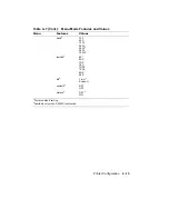
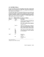
The interface selection (i/f) feature selects the type of interface used to
communicate with the host computer. It must match the interface used by
the host computer, either serial or parallel.
When you select the parallel (CENTRO) interface, you cannot select any
other settings in the INTERFACE menu. The other features in this menu
apply only to the serial interface and are not displayed when you select the
parallel interface.
When you select the serial interface, you must also select certain other
values in the INTERFACE menu in order to match the features of the host
computer. The additional features are described next.
4.5.6.2 Baud Rate (baud)
The baud rate (baud) feature sets the transmit and receive speed the printer
uses to communicate with the host computer. The printer speed must match
the speed used by the host computer.
4.5.6.3 RS232C Data Format (rsmode)
The RS232C data format (rsmode) feature determines the data format the
printer uses to communicate with the host computer. The first part of the
value (7 or 8) is the number of data bits the printer expects to see in each
character it receives. The second part of the value is the type of parity
(checking) bit the printer looks for in each character. A parity check is a
method used to detect errors when data is sent over a communications line.
Some systems use an odd parity bit to detect errors, while other systems
use an even parity bit. Some systems use no parity bit at all. The third
part of rsmode is the number of stop bits. Some systems use one stop bit
while other systems require two. The format for the data bits, parity bit,
and stop bit(s) must match the format of the host computer in order for the
printer and the host to communicate.
4.5.6.4 Data Terminal Ready (dtr)
The data terminal ready (dtr) feature uses hardware to regulate the flow
of data to the input buffer of the printer. The printer transmits a signal
to the DTR line of the serial port when it is ready to receive data. This is
sometimes referred to as the hardware handshaking protocol.
For Digital systems, the dtr feature should always be set to the fixed high
value. When the DTR signal is fixed high (Fix-H), it indicates to the system
that the printer is ‘‘present.’’
Printer Configuration
4–25
Содержание DEClaser 1100 Series
Страница 18: ...Figure 1 1 Components Front Right Side View MLO 005960 1 2 Operator s Guide ...
Страница 21: ...Figure 1 2 Components Rear Left Side View MLO 005961 Printer Components 1 5 ...
Страница 23: ...Figure 1 3 Components Inside the Printer MLO 005962 Printer Components 1 7 ...
Страница 31: ...2 Pull the extension tray straight out MLO 005815 Operating Information 2 5 ...
Страница 34: ...3 Tap the stack of paper on a flat surface to align the edges MLO 005967 2 8 Operator s Guide ...
Страница 40: ...2 Align the stack of envelopes by tapping them on a flat surface MLO 005970 2 14 Operator s Guide ...
Страница 65: ...Figure 3 1 Control Panel MLO 005830 3 2 Operator s Guide ...
Страница 123: ...2 Remove any paper remaining in the paper tray and close the extension tray MLO 005981 Troubleshooting 6 15 ...
Страница 141: ...4 Insert the printed cleaning paper into the paper tray with the printed side facing up MLO 005988 Maintenance 7 11 ...
Страница 177: ...Figure C 2 Serial Connections to Modem MLO 004885 Specifications C 5 ...
Страница 180: ...Figure C 4 Parallel Pin Assignment MLO 004886 Figure C 5 Parallel Connections MLO 005828 C 8 Operator s Guide ...

