Table 1–1 (Cont.): Printer Components: Front/Right-Side View
Component
Function
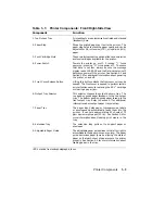
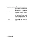
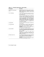
10. Fixing Assembly Cover
The fixing assembly cover can be opened to access
paper jams that occur in the fixing assembly. See
Section 6.7 for more information about clearing paper
jams.
WARNING: The rollers in the fixing assembly may be
hot. Be careful when accessing this area.
11. Front Cover
The front cover opens so you can replace the EP-L
cartridge, adjust the print density, and access printer
components.
12. Control Panel
The control panel consists of a message display,
indicator lights, and a keypad.
The control panel
provides information on printer status and can be
used to perform certain printer functions such as
resetting the printer or configuring the printer. See
Chapter 3 for additional information about using
the control panel while printing.
Chapter 4 has
information about using the control panel to configure
the printer.
13. Front Output Tray
(not shown)
The front output tray is used when you want to
stack documents faceup. Refer to Section 2.7.2 for
additional information about installing and selecting
the front output tray.
1–4
Operator’s Guide
Содержание DEClaser 1100 Series
Страница 18: ...Figure 1 1 Components Front Right Side View MLO 005960 1 2 Operator s Guide ...
Страница 21: ...Figure 1 2 Components Rear Left Side View MLO 005961 Printer Components 1 5 ...
Страница 23: ...Figure 1 3 Components Inside the Printer MLO 005962 Printer Components 1 7 ...
Страница 31: ...2 Pull the extension tray straight out MLO 005815 Operating Information 2 5 ...
Страница 34: ...3 Tap the stack of paper on a flat surface to align the edges MLO 005967 2 8 Operator s Guide ...
Страница 40: ...2 Align the stack of envelopes by tapping them on a flat surface MLO 005970 2 14 Operator s Guide ...
Страница 65: ...Figure 3 1 Control Panel MLO 005830 3 2 Operator s Guide ...
Страница 123: ...2 Remove any paper remaining in the paper tray and close the extension tray MLO 005981 Troubleshooting 6 15 ...
Страница 141: ...4 Insert the printed cleaning paper into the paper tray with the printed side facing up MLO 005988 Maintenance 7 11 ...
Страница 177: ...Figure C 2 Serial Connections to Modem MLO 004885 Specifications C 5 ...
Страница 180: ...Figure C 4 Parallel Pin Assignment MLO 004886 Figure C 5 Parallel Connections MLO 005828 C 8 Operator s Guide ...

