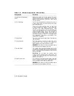
Table 1–2: Printer Components: Rear/Left-Side View
Component
Function
1. Air Vent
The cooling fan exhausts air through this vent. Be
sure that the printer has adequate space around it to
ensure proper ventilation.
2. Memory Board Access Cover
Optional RAM (random-access memory) can be added
to the printer. This access cover allows you to install
the optional memory boards easily.
Refer to the
instructions on the memory board packaging for the
installation procedure.
3. Power Cord Receptacle
This is where the power cord is connected to the
printer.
4. Parallel (Centronics)
Interface Cable Connector
This connector is used when the interface cable from
the host computer is a parallel cable. Refer to the
DEClaser 1100 Printer Installation Guide for more
information about connecting your computer to the
printer.
5. Video Interface Connector
This connector is used to connect an external video
controller to the printer.
Input from an external
controller allows the DEClaser 1100 to print custom
graphic applications at maximum speed.
Consult
your external video controller documentation for
interface information.
6. Serial (RS232C)
Interface Cable Connector
This connector is used when the interface cable from
the host computer is a serial cable. Refer to the
DEClaser 1100 Printer Installation Guide for more
information about connecting your computer to the
printer.
1–6
Operator’s Guide
Содержание DEClaser 1100 Series
Страница 18: ...Figure 1 1 Components Front Right Side View MLO 005960 1 2 Operator s Guide ...
Страница 21: ...Figure 1 2 Components Rear Left Side View MLO 005961 Printer Components 1 5 ...
Страница 23: ...Figure 1 3 Components Inside the Printer MLO 005962 Printer Components 1 7 ...
Страница 31: ...2 Pull the extension tray straight out MLO 005815 Operating Information 2 5 ...
Страница 34: ...3 Tap the stack of paper on a flat surface to align the edges MLO 005967 2 8 Operator s Guide ...
Страница 40: ...2 Align the stack of envelopes by tapping them on a flat surface MLO 005970 2 14 Operator s Guide ...
Страница 65: ...Figure 3 1 Control Panel MLO 005830 3 2 Operator s Guide ...
Страница 123: ...2 Remove any paper remaining in the paper tray and close the extension tray MLO 005981 Troubleshooting 6 15 ...
Страница 141: ...4 Insert the printed cleaning paper into the paper tray with the printed side facing up MLO 005988 Maintenance 7 11 ...
Страница 177: ...Figure C 2 Serial Connections to Modem MLO 004885 Specifications C 5 ...
Страница 180: ...Figure C 4 Parallel Pin Assignment MLO 004886 Figure C 5 Parallel Connections MLO 005828 C 8 Operator s Guide ...

