Figures
1–1
Components: Front/Right-Side View . . . . . . . . . . . . . . . . . . .
1–2
1–2
Components: Rear/Left-Side View . . . . . . . . . . . . . . . . . . . . .
1–5
1–3
Components: Inside the Printer . . . . . . . . . . . . . . . . . . . . . . .
1–7
1–4
Operating Space: Top View . . . . . . . . . . . . . . . . . . . . . . . . . . 1–10
1–5
Operating Space: Side View . . . . . . . . . . . . . . . . . . . . . . . . . . 1–10
2–1
Output Tray Selections . . . . . . . . . . . . . . . . . . . . . . . . . . . . . 2–18
2–2
Test Print A . . . . . . . . . . . . . . . . . . . . . . . . . . . . . . . . . . . . . . 2–27
2–3
Test Print B . . . . . . . . . . . . . . . . . . . . . . . . . . . . . . . . . . . . . . 2–30
2–4
Font List . . . . . . . . . . . . . . . . . . . . . . . . . . . . . . . . . . . . . . . . 2–32
3–1
Control Panel . . . . . . . . . . . . . . . . . . . . . . . . . . . . . . . . . . . . .
3–2
4–1
Sample Menu . . . . . . . . . . . . . . . . . . . . . . . . . . . . . . . . . . . . .
4–1
4–2
Menu Display . . . . . . . . . . . . . . . . . . . . . . . . . . . . . . . . . . . . .
4–5
4–3
Operating Memory . . . . . . . . . . . . . . . . . . . . . . . . . . . . . . . . .
4–7
4–4
Operational Flow Chart . . . . . . . . . . . . . . . . . . . . . . . . . . . . .
4–11
5–1
Unacceptable Labels . . . . . . . . . . . . . . . . . . . . . . . . . . . . . . .
5–9
6–1
Paper Jam Areas . . . . . . . . . . . . . . . . . . . . . . . . . . . . . . . . . . 6–13
7–1
Rocking the EP-L Cartridge . . . . . . . . . . . . . . . . . . . . . . . . . .
7–3
C–1
RS232C Pin Assignments . . . . . . . . . . . . . . . . . . . . . . . . . . . .
C–4
C–2
Serial Connections to Modem . . . . . . . . . . . . . . . . . . . . . . . . .
C–5
C–3
Serial Connections Without Modem . . . . . . . . . . . . . . . . . . . .
C–6
C–4
Parallel Pin Assignment . . . . . . . . . . . . . . . . . . . . . . . . . . . .
C–8
C–5
Parallel Connections . . . . . . . . . . . . . . . . . . . . . . . . . . . . . . .
C–8
Tables
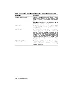
1–1
Printer Components: Front/Right-Side View . . . . . . . . . . . . .
1–3
1–2
Printer Components: Rear/Left-Side View . . . . . . . . . . . . . . .
1–6
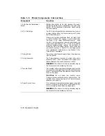
1–3
Printer Components: Internal View . . . . . . . . . . . . . . . . . . . .
1–8
2–1
Changing Page Format Size . . . . . . . . . . . . . . . . . . . . . . . . . .
2–11
2–2
Test Print A . . . . . . . . . . . . . . . . . . . . . . . . . . . . . . . . . . . . . . 2–28
2–3
Printing Test Print A . . . . . . . . . . . . . . . . . . . . . . . . . . . . . . . 2–29
2–4
Printing Test Print B . . . . . . . . . . . . . . . . . . . . . . . . . . . . . . . 2–31
2–5
Printing the Font List . . . . . . . . . . . . . . . . . . . . . . . . . . . . . . 2–33
2–6
Entering Control Representation Mode . . . . . . . . . . . . . . . . . 2–35
2–7
Resetting the Printer . . . . . . . . . . . . . . . . . . . . . . . . . . . . . . . 2–36
vii
Содержание DEClaser 1100 Series
Страница 18: ...Figure 1 1 Components Front Right Side View MLO 005960 1 2 Operator s Guide ...
Страница 21: ...Figure 1 2 Components Rear Left Side View MLO 005961 Printer Components 1 5 ...
Страница 23: ...Figure 1 3 Components Inside the Printer MLO 005962 Printer Components 1 7 ...
Страница 31: ...2 Pull the extension tray straight out MLO 005815 Operating Information 2 5 ...
Страница 34: ...3 Tap the stack of paper on a flat surface to align the edges MLO 005967 2 8 Operator s Guide ...
Страница 40: ...2 Align the stack of envelopes by tapping them on a flat surface MLO 005970 2 14 Operator s Guide ...
Страница 65: ...Figure 3 1 Control Panel MLO 005830 3 2 Operator s Guide ...
Страница 123: ...2 Remove any paper remaining in the paper tray and close the extension tray MLO 005981 Troubleshooting 6 15 ...
Страница 141: ...4 Insert the printed cleaning paper into the paper tray with the printed side facing up MLO 005988 Maintenance 7 11 ...
Страница 177: ...Figure C 2 Serial Connections to Modem MLO 004885 Specifications C 5 ...
Страница 180: ...Figure C 4 Parallel Pin Assignment MLO 004886 Figure C 5 Parallel Connections MLO 005828 C 8 Operator s Guide ...

