9-8
DECcolorwriter 1000
9
Checks and Adjustments
Switch and interrupt sensor checks
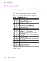
There are six switch check modes to test a total of 21 switches and interrupt sensors. The
modes test the following switches:
Note
Figure 1-3 illustrates the locations of the print engine's sensors.
Mode 1
Cover open sensor
Cover open sensor
TEST button
Second feeder installed sensor
Mode 2
Head lift sensor 1
Head lift sensor 2
Transfer roll core sensor 1 (left)
Transfer roll core sensor 2 (right)
Mode 3
Tray switch 1 (standard)
Tray switch 2 (standard)
Tray switch 3 (standard)
Paper empty sensor (standard tray)
Mode 4
Tray switch 1 (second feeder)
Tray switch 2 (second feeder)
Tray switch 3 (second feeder)
Paper empty sensor (second feeder tray)
Mode 5
Paper-pass sensor 1
Paper-pass sensor 2
Paper exit sensor
Drum home position sensor
Mode 6
Transfer roll low sensor
1.
Turn off the printer.
2.
Remove the rear cabinet panel to access the engine control board. Refer to
the Chapter 8 topic “Printer cabinet panels” on page 8-3.
3.
Press and hold the TEST button and turn on the printer. Release the TEST
button. The printer is now in service mode.
4.
Set all the DIP 1 switches off.
5.
Select the test mode you want from the list above and then set the DIP
switches to activate the test mode you want:
Mode 1: Set DIP Switch 1-4 on.
Mode 2: Set DIP Switches 1-4 and 1-7 on.
Mode 3: Set DIP Switches 1-4 and 1-6 on.
Mode 4: Set DIP Switches 1-4, 1-6 and 1-7 on.
Mode 5: Set DIP Switches 1-4 and 1-5 on.
Mode 6: Set DIP Switches 1-4, 1-5 and 1-7 on.
Содержание DECcolorwriter 1000
Страница 11: ...Service Manual xi...
Страница 16: ...Service Manual xv...
Страница 56: ...2 24 DECcolorwriter 1000 2 Installing the Printer and Drivers...
Страница 64: ...3 8 DECcolorwriter 1000 3 Verifying the Printer and Host Connections...
Страница 70: ...4 6 DECcolorwriter 1000 4 Key Operator Training...
Страница 170: ...8 46 DECcolorwriter 1000 8 FRU Disassembly Assembly...
Страница 190: ...9 20 DECcolorwriter 1000 9 Checks and Adjustments...
Страница 193: ...Service Manual A 3 Field Replaceable Units List A Figure A 1 The printer exterior FRUs 8699 76A 1 2 3 4 5 6 7 8 9...
Страница 195: ...Service Manual A 5 Field Replaceable Units List A...
Страница 198: ...A 8 DECcolorwriter 1000 A Field Replaceable Units List...
Страница 204: ...C 6 DECcolorwriter 1000 C Wiring Diagrams...
Страница 208: ...D 4 DECcolorwriter 1000 D Test Pattern Generator...


