6-30
DECcolorwriter 1000
6
Troubleshooting
Image processor self-diagnostics
Image processor rear panel switches for self-testing
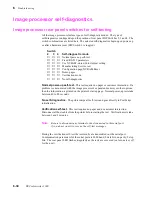
All the image processors feature types of self-diagnostic modes. The type of
self-diagnostics run depend upon the position of rear panel DIP Switches 2, 3 and 4. The
switch combinations are listed here. The selected self-diagnostics begin upon power-up
or after a hardware reset (DIP Switch 1 is toggled).
Switch
2 3 4
Self-diagnostic mode
↓
↓
↓
Normal power-up self-test
↑
↓
↓
Fixed RS-232 parameters
↓
↑
↓
Use NVRAM-stored Color Adjust setting
↑
↑
↓
Manufacturing Service test
↓
↓
↑
Configuration page/NVRAM Reset
↑
↓
↑
Demo pages
↓
↑
↑
Verification mode
↑
↑
↑
No self-diagnostics
Normal power-up self-test.
This test requires no paper or customer interaction. If a
problem is encountered with the image processor's expansion memory or other options,
then the information is printed on the printer's start up page. Normal power-up tests take
between 40 to 80 seconds.
No self-diagnostics.
The printer skips all self-tests and goes directly to PostScript
initialization.
Verification self-test.
This test requires no paper and no customer interaction.
Disconnect all host cables from the printer before starting the test. Verification tests take
between 1 and 2 minutes.
Note
Be sure to disconnect any terminal or host connected to the serial port
if you do not want it to receive the self-test messages.
During the verification self-test the test results are transmitted out the serial port.
Communication parameters for the serial port are 9600 baud, 8 data bits, no parity, 2 stop
bits. The rear panel LED flashes irregularly as the tests are executed (on for one test, off
for the next).
Содержание DECcolorwriter 1000
Страница 11: ...Service Manual xi...
Страница 16: ...Service Manual xv...
Страница 56: ...2 24 DECcolorwriter 1000 2 Installing the Printer and Drivers...
Страница 64: ...3 8 DECcolorwriter 1000 3 Verifying the Printer and Host Connections...
Страница 70: ...4 6 DECcolorwriter 1000 4 Key Operator Training...
Страница 170: ...8 46 DECcolorwriter 1000 8 FRU Disassembly Assembly...
Страница 190: ...9 20 DECcolorwriter 1000 9 Checks and Adjustments...
Страница 193: ...Service Manual A 3 Field Replaceable Units List A Figure A 1 The printer exterior FRUs 8699 76A 1 2 3 4 5 6 7 8 9...
Страница 195: ...Service Manual A 5 Field Replaceable Units List A...
Страница 198: ...A 8 DECcolorwriter 1000 A Field Replaceable Units List...
Страница 204: ...C 6 DECcolorwriter 1000 C Wiring Diagrams...
Страница 208: ...D 4 DECcolorwriter 1000 D Test Pattern Generator...

