8-30
DECcolorwriter 1000
8
FRU Disassembly/Assembly
Paper-pass sensor 2 and tray sensor
Paper-pass sensor 2 and the paper tray sense switches are located inside the paper-feed
module. You follow the same basic procedure to access either sensor.
1.
Power down the printer and remove the power cord.
2.
Remove the paper-feed module as explained in the previous procedure
“Paper-feed module” on page 8-5.
3.
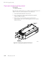
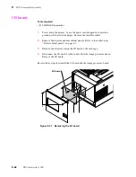
Remove the two screws securing the paper-feed circuit board to the
paper-feed module. (One screw is reached through an access hole.) Slide the
board out of the way.
Tools required
n
#1 POSIDRIV® screwdriver
Figure 8-26 Removing the paper-feed circuit board
8699-24
Paper-feed
module
Paper-feed
circuit board
3
Содержание DECcolorwriter 1000
Страница 11: ...Service Manual xi...
Страница 16: ...Service Manual xv...
Страница 56: ...2 24 DECcolorwriter 1000 2 Installing the Printer and Drivers...
Страница 64: ...3 8 DECcolorwriter 1000 3 Verifying the Printer and Host Connections...
Страница 70: ...4 6 DECcolorwriter 1000 4 Key Operator Training...
Страница 170: ...8 46 DECcolorwriter 1000 8 FRU Disassembly Assembly...
Страница 190: ...9 20 DECcolorwriter 1000 9 Checks and Adjustments...
Страница 193: ...Service Manual A 3 Field Replaceable Units List A Figure A 1 The printer exterior FRUs 8699 76A 1 2 3 4 5 6 7 8 9...
Страница 195: ...Service Manual A 5 Field Replaceable Units List A...
Страница 198: ...A 8 DECcolorwriter 1000 A Field Replaceable Units List...
Страница 204: ...C 6 DECcolorwriter 1000 C Wiring Diagrams...
Страница 208: ...D 4 DECcolorwriter 1000 D Test Pattern Generator...

