C-4
DECcolorwriter 1000
C
Wiring Diagrams
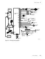
Figure C-1. Print engine control board connector diagram
8699-81A
. .
. .
. .
. .
. .
. .
. .
. .
. .
. .
. .
. .
. .
. .
. .
. .
. .
. .
. .
. .
. .
. .
. .
. .
. .
. .
..
.
.
.
.
.
..
.
.
.
.
.
.
.
.
.
.
.
.
Thermal head
lift motor
Front panel
Core sensor, left
Transfer roll
sensor
Core sensor, right
Paper-clamp sensor
Paper-feed
circuit board
Paper-feed
motor
2
1
40
39
1
3
1
2
81
2
13
14
CN7
CN8
CN4
Drum
motor
Transfer roll
mark sensor
Thermal head
position
sensor
Drum-home-
position sensor
.
.
.
.
.
.
.
.
Thermal head
CN2
CN3
CN5
CN6
Thermal head
fan
Содержание DECcolorwriter 1000
Страница 11: ...Service Manual xi...
Страница 16: ...Service Manual xv...
Страница 56: ...2 24 DECcolorwriter 1000 2 Installing the Printer and Drivers...
Страница 64: ...3 8 DECcolorwriter 1000 3 Verifying the Printer and Host Connections...
Страница 70: ...4 6 DECcolorwriter 1000 4 Key Operator Training...
Страница 170: ...8 46 DECcolorwriter 1000 8 FRU Disassembly Assembly...
Страница 190: ...9 20 DECcolorwriter 1000 9 Checks and Adjustments...
Страница 193: ...Service Manual A 3 Field Replaceable Units List A Figure A 1 The printer exterior FRUs 8699 76A 1 2 3 4 5 6 7 8 9...
Страница 195: ...Service Manual A 5 Field Replaceable Units List A...
Страница 198: ...A 8 DECcolorwriter 1000 A Field Replaceable Units List...
Страница 204: ...C 6 DECcolorwriter 1000 C Wiring Diagrams...
Страница 208: ...D 4 DECcolorwriter 1000 D Test Pattern Generator...


