9-10
DECcolorwriter 1000
9
Checks and Adjustments
Calibrating the transfer roll mark sensors (reflective sensors)
1.
Turn off the printer. Ensure that a 3-Color transfer roll is installed.
2.
Remove the rear cabinet panel to access the engine control board. Refer to
the Chapter 8 topic “Printer cabinet panels” on page 8-3.
3.
Press and hold the TEST button and turn on the printer. Release the TEST
button. The printer is now in service mode.
4.
Set all the DIP 1 Switches off.
5.
Set DIP Switches 1-4, 1-5 and 1-6 on.
6.
Set DIP Switch 1-3 on to start the test. LEDs ERROR and JAM blink rapidly
to indicate that the sensor test is active.
7.
Press the TEST button to advance the transfer roll and calibrate the sensors
for the amount of reflected light they detect from the white reflection plate
(located beneath the sensors). LED READY will blink rapidly.
8.
Set DIP Switch 1-3 off to exit the mode.
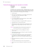
Calibrating the paper clamp sensor (reflective sensor)
1.
Turn off the printer. Ensure that the paper tray is filled.
2.
Remove the rear cabinet panel to access the engine control board. Refer to
the Chapter 8 topic “Printer cabinet panels” on page 8-3.
3.
Press and hold the TEST button and turn on the printer. Release the TEST
button. The printer is now in service mode.
4.
Set all the DIP 1 switches off.
5.
Set DIP Switches 1-4, 1-5, 1-6 and 1-7 on.
6.
Set DIP Switch 1-3 on to start the sensor test. LEDs ERROR and JAM blink
rapidly to indicate that the test is active.
7.
Push the TEST button. The printer will pick a sheet of paper and pass it
through the paper path. LED READY will blink rapidly as the paper clamp
sensor is calibrated.
8.
Set DIP Switch 1-3 off to stop the test.
Содержание DECcolorwriter 1000
Страница 11: ...Service Manual xi...
Страница 16: ...Service Manual xv...
Страница 56: ...2 24 DECcolorwriter 1000 2 Installing the Printer and Drivers...
Страница 64: ...3 8 DECcolorwriter 1000 3 Verifying the Printer and Host Connections...
Страница 70: ...4 6 DECcolorwriter 1000 4 Key Operator Training...
Страница 170: ...8 46 DECcolorwriter 1000 8 FRU Disassembly Assembly...
Страница 190: ...9 20 DECcolorwriter 1000 9 Checks and Adjustments...
Страница 193: ...Service Manual A 3 Field Replaceable Units List A Figure A 1 The printer exterior FRUs 8699 76A 1 2 3 4 5 6 7 8 9...
Страница 195: ...Service Manual A 5 Field Replaceable Units List A...
Страница 198: ...A 8 DECcolorwriter 1000 A Field Replaceable Units List...
Страница 204: ...C 6 DECcolorwriter 1000 C Wiring Diagrams...
Страница 208: ...D 4 DECcolorwriter 1000 D Test Pattern Generator...

