8-32
DECcolorwriter 1000
8
FRU Disassembly/Assembly
6.
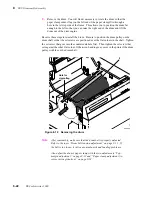
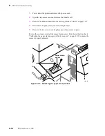
Tray sensor circuit board: Disconnect the tray sensors’ wiring harness.
7.
Straighten the two metal tabs securing the tray sensors’ bracket to the
paper-feed module. Unhinge the bracket to access the tray sensor circuit
board.
8.
Remove the screw securing the paper tray sensor circuit board to the bracket.
Remove the circuit board.
Reverse these steps to reinstall paper-pass sensor 2 and the tray sensor circuit board.
Figure 8-28 Removing the tray sensors circuit board
8699-51
Unhinge
here
Tray sensors
bracket
7
Tray sensors
circuit board
6
8
Содержание DECcolorwriter 1000
Страница 11: ...Service Manual xi...
Страница 16: ...Service Manual xv...
Страница 56: ...2 24 DECcolorwriter 1000 2 Installing the Printer and Drivers...
Страница 64: ...3 8 DECcolorwriter 1000 3 Verifying the Printer and Host Connections...
Страница 70: ...4 6 DECcolorwriter 1000 4 Key Operator Training...
Страница 170: ...8 46 DECcolorwriter 1000 8 FRU Disassembly Assembly...
Страница 190: ...9 20 DECcolorwriter 1000 9 Checks and Adjustments...
Страница 193: ...Service Manual A 3 Field Replaceable Units List A Figure A 1 The printer exterior FRUs 8699 76A 1 2 3 4 5 6 7 8 9...
Страница 195: ...Service Manual A 5 Field Replaceable Units List A...
Страница 198: ...A 8 DECcolorwriter 1000 A Field Replaceable Units List...
Страница 204: ...C 6 DECcolorwriter 1000 C Wiring Diagrams...
Страница 208: ...D 4 DECcolorwriter 1000 D Test Pattern Generator...

