background image

3 - MAINTENANCE

53

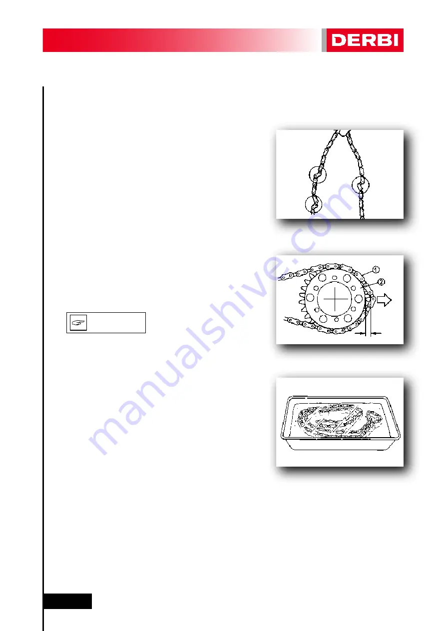
TRANSMISSION CHAIN

1. Inspect:

- The chain for rigidity.

Rigidity => Clean and lubricate or renew.

2. Inspect:

- Transmission chain(1).
- Rear sprocket (2).
- Sprocket.

More than ½ tooth of wear => Renew the chain.

IT IS RECOMMENDED TO RENEW 
THE COMPLETE TRANSMISSION 
KIT AND NOT JUST THE CHAIN.

3. Clean:

- The transmission  chain.

- Place the chain in a container with petrol, and brush it to 
remove as much of the dirt as possible.

- Then dry and lubricate it. 

Lubricant for the transmission chain:
Spray grease for chains.

N.B.

Содержание GPR 125 Racing

Страница 1: ...WORKSHOP MANUAL GPR 125 4 stroke ...

Страница 2: ...N AND MAINTENANCE IDENTIFICATION OF SETS REMOVING THE ENGINE FROM THE FRAME DISMANTLING THE ENGINE INSPECTING THE ENGINE ELEMENTS ASSEMBLING THE ENGINE FITTING THE ENGINE INTO THE FRAME DISMANTLING THE CARBURETTOR ASSEMBLING THE CARBURETTOR CHECKING LEVEL OF THE FLOAT CHAMBER CHECKING THE VACUM VALVE AND TAPERED NEEDLE CHECKING THE AUTOMATIC CHOKE ENGINE 4 9 10 13 16 17 26 31 34 36 48 51 52 83 85 ...

Страница 3: ...WHEEL FRONT SUSPENSION STEERING REAR WHEEL REAR SUSPENSION FRONT BRAKE REAR BRAKE GENERAL INDICATIONS LOCATING ELECTRICAL COMPONENTS WIRING DIAGRAM CHARGING SYSTEM IGNITION SYSTEM STARTER MOTOR SYSTEM INSTRUMENT PANEL LIGHTING AND INDICATING FITTING NEW COMPONENTS INSPECTING THE BATTERY AND FUSES 6 7 8 9 10 169 171 175 179 181 185 187 189 195 198 200 203 211 221 223 224 225 226 227 228 235 241 245...

Страница 4: ...e a basic knowledge of mechanics and of the methods inherent in the technique of vehicle repair Signifi cant variations in the characteristics of the machines or in the specific repair operations will be communicated by means of updates to this manual Completely satisfactory work cannot however be carried out without the availability of suitable facilities and tools which is why we ask you to cons...

Страница 5: ...extraction dismantling assembly repair and checking procedures organized step by step in sequence Each chapter is divided into sections whose titles appear at the top of each page The titles of the subsections appear in a smaller format than the section titles Each operation is accompanied by photographs or illustrations Numbering corresponding to the chapter 1 2 3 4 4 3 1 2 ...

Страница 6: ...T HAND SIDE facing forwards RIGHT HAND SIDE facing forwards VIEWS OF THE MACHINE Whenever Right hand or Left hand Side are specified in this manual it is understood as meaning facing forward i e in the riding direction N B ...

Страница 7: ...s located to the right of the steering column MANUFACTURER S PLATE The manufacturer s plate is located to the right of the steering column It includes information about the exhaust system s noise emissions useful in MOT inspec tions ENGINE SERIAL NUMBER xxxx The frame serial number is on the rear of the chassis ...

Страница 8: ...ORMATION 8 1 GENERAL INFORMATION SAFETY REGULATIONS MAINTENANCE REGULATIONS SPECIAL TOOLS FOR THE ENGINE SPECIAL TOOLS FOR THE CHASSIS TECHNICAL DATA TORQUE TIGHTENING VALUES 9 10 13 16 17 26 1 1 1 2 1 3 1 4 1 5 1 6 ...

Страница 9: ... handling used oil Petrol is extremely inflammable and in certain conditions can be explosive Do not smoke and avoid sparks or other points of ignition in the work area Clean brake pads in a well ventilated place DO NOT use compressed air to clean brake pads or brake calli pers Although the dust does not contain asbestos its inhalation can cause respiratory illnesses Brake liquid attacks painted s...

Страница 10: ...ns use only tools with metric measurements Metric screws nuts and bolts are not interchangeable with imperial measurement joining devices Using unsuitable tools and joining devices may damage the machine In the case of work on the machine s electrical circuitry check that electrical connections have been correc tly fitted especially the earth connections Use only genuine DERBI spare parts For all ...

Страница 11: ...ut once they have been tightened to the specified torque WHEN FITTING BEARINGS EN SURE THAT THE SAME PRESSURE IS APPLIED TO BOTH RACES TO AVOID DAMAGING THEM Fit bearings and retaining rings in such a way that the manufac turers marks remain visible On fitting retaining rings applying a thin film of light lithium soap based grease to their edges Where appropriate apply oil generously when fitting ...

Страница 12: ...r parts submitted to natural wear in pairs Paired parts must always be reassem bled or replaced together While dismantling the motorcycle clean all the parts and lay them out on trays in the order dismantled This speeds up reass embly and ensures the correct fitting of all the parts KEEP ALL PARTS WELL AWAY FROM ANY SOURCE OF IGNITION CIGA RETTES FLAMES SPARKS ETC CAUTION N B WARNING ...

Страница 13: ...cial tools thereby avoiding damage caused by the use of unsuitable tools or improvised techniques Ref 864486 Camshaft sprocket locking tool Ref 864487 Crankshaft sprocket locking tool Ref 864567 Set of camshaft locking keys Ref 864592 TDC measuring tool must be accompanied by a dial depth gauge This is used to calculate the thickness of the cylinder base gasket to be used ...

Страница 14: ... Set of tools for 125cc 4 stroke 4v engine THE SET OF TOOLS FOR THE ENGI NE DOES NOT INCLUDE TOOL REF 866380 Ref 865259 Camshaft crown wheel locking tool Ref 865260 Magneto flywheel locking tool Ref 865261 Tool for supporting piston N B ...

Страница 15: ...1 GENERAL INFORMATION 15 Ref 866380 Tool kit A B C for extracting and fitting water pump oil seal Ref 00H05300041 Clutch bell housing locking tool Ref 864868 Magneto flywheel extractor tool ...

Страница 16: ...ollowing special tools are needed for assembly and for com plete and exact adjustments Only use the proper special tools thereby avoiding damage caused by the use of unsuitable tools or improvised techniques Ref 866714 Tool for adjusting the swinging arm nut ...

Страница 17: ...tio 2nd gear ratio 3rd gear ratio 4th gear ratio 5th gear ratio 6th gear ratio Final transmission ratio Type of chain 1353 mm 1968 mm 720 mm 810 mm 135 Kg 58 mm x 47 mm 124 2 cm3 15 HP at 9 250 rpm Single cylinder 4 stroke 4 valves Euro 3 Double overhead camshaft DOHC chain driven 12 1 Cast iron Cast aluminium Semi wet crankshaft Liquid 1680 50 rpm Manual 6 gears Chain driven Secondary air system ...

Страница 18: ...filter Total engine oil complete dismantling of the engine Type of engine oil recommended Engine oil viscosity Petrol Fuel tank capacity Coolant in radiator Coolant in expansion chamber up to max Recommended coolant Brake fluid NGK CR8 EB 0 7 0 8 mm Three phase magneto 13v 15v at 8 000 rpm Electronic CDI type FTX7L BS 12v 6Ah MF type Electric 1150 ml 1200 ml AGIP TECH 4T SAE 10W 40 Lead free 95 oc...

Страница 19: ...G TYPE 1st compression ring Type Dimension BxT 2nd compression ring Type Dimension BxT 3rd oil scraper ring Dimension BxT PISTON RING GAP 1st compression ring 2nd compression ring 3rd oil scraper ring 57 953 57 960 mm 57 960 57 967 mm 57 967 57 974 mm 57 974 57 981 mm 7 5 mm 15 003 15 008 mm 14 997 15 00 mm 14 995 mm Tapered 1 x 2 5 mm Tapered 1 2 x 2 5 mm 2 x 2 5 mm 0 2 0 35 mm 0 2 0 35 mm 0 2 0 ...

Страница 20: ... Inlet Exhaust MAXIMUM CAMSHAFT AXIAL PLAY Inlet Exhaust CAM SIZE Inlet A Inlet B Inlet lifted C Exhaust A Exhaust B Exhaust lifted C TIMING CHAIN Type Timing chain tensioner 58 010 58 017 mm 58 017 58 024 mm 58 024 58 031 mm 58 031 58 038 mm 0 05 mm 0 050 0 064 mm 0 05 mm more than 15 kg cm2 13 Kg cm2 0 012 0 015 mm 0 015 0 020 mm 0 008 mm 0 008 mm 0 4 mm 0 4 mm 31 44 31 54 mm 23 95 24 05 mm 7 49...

Страница 21: ...LVE STEM DIAMETER Inlet Exhaust VALVE GUIDE INTERNAL DIAMETER A Inlet Exhaust VALVE STEM GUIDE PLAY LIMIT Inlet Exhaust VALVE WARP Inlet Exhaust 21 90 22 05 mm 18 70 18 85 mm 2 33 2 63 mm 2 82 3 12 mm 3 97 3 98 mm 3 96 3 97 mm 3 97 3 98 mm 3 97 3 98 mm 0 015 0 042 mm 0 015 0 042 mm 0 01 mm 0 01 mm A B A ...

Страница 22: ...ECTING ROD Connecting rod side play B Diameter of the connecting rod Standard Limit CLUTCH Thickness of driving disks Number of driving disks Thickness of driven disks Number of driven disks Driven disk flatness service limit Free length of clutch springs Number of springs Clutch freeing method 33 24 mm 33 24 mm 26 mm 26 mm 101 87 116 13 N 10 19 11 61 Kgf 101 87 116 13 N 10 19 11 61 Kgf 46 87 47 0...

Страница 23: ...ke operation Resistance value PTC Choke needle travel KEIHIN CVK Ø30 100 50 5 0 mm 2 8 mm NDYD 2 490 mm 35 130 Float parallel to the base of the float chamber 33 ml to 35 ml Automatic PTC 20 Ω at 24ºC 10 5 mm Initial thermostat opening temperature Total thermostat opening temperature Radiator cap opening pressure Electric fan on temperature Electric fan off temperature Temperature sensor resistanc...

Страница 24: ...nger Rear tyre pressure for rider only For rider only With pillion passenger Minimum tyre tread depth 0 5 mm 0 6 mm 0 05 mm 0 2 mm Aleación de aluminio 1 9 bar 2 bar 2 bar 2 2 bar 1 6 mm WHEEL RIMS AND TYRES Oil pressure manometer connected in sensor Pump with 2 rotors Oil suction rotor Thickness Oil pumping rotor Thickness Radial clearance 1 between rotor points Radial clearance 2 between rotor p...

Страница 25: ...ding 25ºC 5º C Resistance of the top coil secondary winding 25ºC 5º C Resistance of the spark plug connector cap 20ºC NGK CR8 EB 0 7 0 8 mm 0º 5º 7º 9º 19º 21º 23º 105 124 Ω 0 21 Ω 0 025 Ω 3 1 KΩ 0 31 KΩ 5 KΩ BRAKES IGNITION SYSTEM Resistance between phases of charging coil 20ºC Output voltage between magneto phases measured at the regulator connector while discon nected from the latter Idling 1 7...

Страница 26: ...ions tighten assemblies with various fixing devices progressively and in a crossed or alternating manner until the specified torque is reached Unless stated otherwise the specified torques require threads to be clean and dry Components should be at room temperature 1 6 TIGHTENING TORQUES GENERAL TORQUE SPECIFICATION TYPE 8 8 Kgf m BOLT M6x1 M8x1 25 M10x1 5 M12x1 5 M12x1 75 M14x1 5 M14x2 N m 8 10 1...

Страница 27: ...SUREMENT QT TIGHTENING TORQUE Kgf m N m Obs Bolt Bolt Bolt Bolt Bolt Bolt Clip Bolt Bolt Bolt Cover Bolt Bolt Bolt Bolt Nut Nut Nut Bolt Bolt Bolt Bolt Bolt M10 M6 M6 M8 M8 M8 M6 M6 M6 M10 M6 M5 M5 M6 M56x1 5 M10 M6 M5 M12 M10 M12 M6 M5 M5 M6 M6 M18X1 5 M28X1 1 4 8 1 1 4 2 1 3 2 1 2 1 3 1 1 1 1 10 5 1 1 1 1 3 1 1 2 1 1 1 2 1 4 1 1 2 1 1 2 2 5 2 7 2 5 2 7 2 7 90 1 1 1 3 1 2 1 8 1 1 1 3 1 1 2 0 8 1 ...

Страница 28: ...s bottom securing device Rear sub chassis chassis sec device Rear sub chassis chassis sec device Engine cradle sec device Cylinder head chassis brackets securing device Engine cylinder head brackets sec device Swinging arm chassis adjustment nut sec device Swinging arm chassis shaft sec device Front footrest chassis bracketsec device Front footrest bracket bracket sec dev Pillion passenger footres...

Страница 29: ...s to chassis sec dev Var metal items to chassis sec dev M8x125 8 8 M5x80 8 8 M8x125 8 8 M8x125 8 8 M14x150 M10x150 8 8 M6x100 10 9 M14x150 8 8 M6x100 12 9 M6x100 10 9 M6x100 10 9 M6x100 8 8 M6x100 10 9 M6x100 10 9 M6x100 8 8 M8x125 8 8 M10x125 8 8 M6x100 8 8 M8x125 8 8 M8x125 8 8 M6x100 M14x150 M8x125 8 8 M5x80 8 8 M8x125 12 9 M5 M6 M5x80 M6x100 M8x125 M5x80 M6x100 Bolt Bolt Bolt Bolt Bolt Bolt Bo...

Страница 30: ...2 PDI Pre delivery inspection 30 2 PDI Pre delivery inspection PDI Pre delivery inspection 31 2 1 ...

Страница 31: ... lever and check functioning SPARK PLUG Tighten check connector cap ELECTRICAL SYSTEM Check and adjust headlight s Check sidelight instrument panel lights brake light turn indicators horn and instrument panel indicator lights LUBRICATION Lubricate elements indicated in the User s Manual CHECK THE FOLLOWING TIGHTENING TORQUES FRONT WHEEL SHAFT 7 8 kgf m FRONT BRAKE CALLIPER 3 5 4 kgf m TOP PLATE CL...

Страница 32: ...g loose or catching BRAKES Check that braking is correct DELIVERY TO CUSTOMER USER MANUAL Explain the importance of reading and understanding the information Highlight sections on safety and maintenance practices Hand over to customer WARRANTY REGISTRATION CARD Fill in the necessary information and hand the copy to the customer then return the original to DERBI immediately HANDLING Explain the cor...

Страница 33: ... MAINTENANCE 33 3 MAINTENANCE LOCATION OF ELEMENTS REMOVING BODYWORK ELEMENTS MAINTENANCE TABLE LUBRICATION POINTS INSPECTION AND MAINTENANCE MAINTENANCE PIECES 34 36 48 51 52 83 3 1 3 2 3 3 3 4 3 5 3 6 ...

Страница 34: ...ENTS RIGHT HAND SIDE VIEW Battery Air filter Throttle cable tensioner Speed sensor Regulator Rectifier CDI ignition unit remove tank Starter relay Adjusting idling speed Oil filter Radiator drain plug Instrument panel multi function button ...

Страница 35: ...INTENANCE 35 LEFT HAND SIDE VIEW Expansion chamber Ignition coil remove tank Main Relay and Fuses Horn Starter motor Engine oil drain plug Engine timing inspection points Engine oil filler plug and dipstick ...

Страница 36: ...CESS IS THE OPPOSITE TO THAT FOR REMO VAL SEAT REMOVAL 1 Remove Insert the ignition key and turn it anticlockwise a 1 4 of a turn 2 Remove The seat by pulling it backwards FITTING 1 Insert The seat flange under the bracket 2 Push The seat forwards 3 Secure Insert the ignition key and turn it clockwise a 1 4 of a turn N B ...

Страница 37: ...SEAT REMOVAL 1 Unscrew The securing bolt A located inside the cowling 2 Remove The seat by pulling it backwards FITTING 1 Insert The seat flange under the bracket 2 Push The seat backwards 3 Secure The seat using the securing bolt A A A ...

Страница 38: ...A securing the cover at the bottom 3 Remove The cover by pulling it backwards COWLING REMOVAL 1 First remove The cowling top cover 2 Unscrew The 8 bolts 4 on each side located at the bottom of the cowling 3 Unscrew The 3 bolts one on each side located at the front of the cowling and a central one at the back A A A ...

Страница 39: ...rds BOTTOM TANK COVER REMOVAL same both sides 1 Unscrew The bolt A located at the bottom of the front wheel arch 2 Unscrew The bolt B located at the top of the front wheel arch 3 Unscrew The 2 side bolts C 4 Remove The bottom tank plate by pulling it out A B C ...

Страница 40: ... Unscrew Remove the 4 side bolts A from the bottom fairing 3 Unscrew The 2 bolts B located at the bottom of the cover 4 Remove The plate by passing the prop stand through the hole CYLINDER HEAD PROTECTIVE COVER REMOVAL same both sides 1 Unscrew The bolt securing the cover 2 Remove The cover A B ...

Страница 41: ...2 left hand bolts on the silencer end cover 3 Unscrew The right hand bolt C on the silencer end cover 4 Retirar The cover BEFORE CARRYING OUT THIS OPERATION ENSURE THAT THE SILENCER IS COLD FRONT MUDGUARD REMOVAL 1 Unscrew The clip A from the speed sensor cable 2 Unscrew The 4 bolts B two on each side of the mudguard B A C A B WARNING ...

Страница 42: ...USE IT TO FALL FORWARDS 3 Unscrew and remove the 5 bolts A from the cover and remove 1 bolt B gaining access from inside the front forks COWLING SIDE CLOSING COVER REMOVAL same on both sides 1 First remove The seat The cowling 2 Unscrew The front bolt on the tank and tilt it backwards 3 Unscrew and remove the 3 bolts A from the cover and remove it B A A WARNING ...

Страница 43: ...ove The bubble screen by sliding it upwards PROTECT THE BUBBLE SCREEN TO PREVENT IT FROM BEING DAMA GED RADIATOR AIR DUCTING REMOVAL 1 Unscrew The 2 bolts A securing the ducting on each side 2 Unscrew The bolt B located at the bottom centre The 2 bolts C securing the ducting at the top centre C B A CAUTION ...

Страница 44: ...instrument panel bracket and remove it 3 Disconnect The instrument panel 4 Retirar The plastic clips holding the cables 5 Disconnect The turn indicators 6 Remove The plastic clips holding the cables 7 Disconnect The sidelight B 8 Disconnect The 3 bolts C from the sidelight 9 Remove The plastic clips holding the cables C B A ...

Страница 45: ...it 10 Remove The 2 bolts A from the rear view mirror on each side and remove them 11 Remove The 2 bolts B 1 on each side securing the front central fairing 12 Remove The 3 bolts A from the front fairing bottom bracket B 13 Remove The central front fairing A B A B A ...

Страница 46: ...ES OR SPARKS REMOVAL 1 Remove The front bolt on the tank and tilt it backwards THE SLOSHING PETROL MAY MAKE IT FALL FORWARDS 2 Remove The carburettor inlet pipe A The breather pipe B 3 Unscrew The bolt A and nut B securing the tank 4 Remove The tank REAR MUDGUARD REMOVAL 1 Remove The rear brake hose clip 2 Remove The 3 bolts one in the top centre A A B B A A WARNING WARNING ...

Страница 47: ...Remove The cover by pulling backwards REAR MUDGUARD SUPPLEMENT REMOVAL 1 First remove The top cowling cover The cowling The rear light see chapter on electrical system The number plate light Steps 1 2 and 3 see chapter on electrical system 2 Disconnect The turn indicator connectors A 3 Unscrew The bolt and the nut B from the turn indicators 4 Unscrew The 3 bolts C gaining access to these through t...

Страница 48: ...educed This information applies not only to machines already in service but also new machines in preparation for being sold All technical assistance staff should familiarize themselves with everything in this chapter ENGINE OIL OIL FILTER CARBURETTOR AIR FILTER SPARK PLUG SECONDARY TRANSMISSION chain sprocket crown wheel TIMING CHAIN VALVE ADJUSTMENT COOLANT Level COOLANT ENGINE AND TRANSMISSION X...

Страница 49: ...YCLE X 1000 km odometer Change every 2 years or 20 000 kilometres whichever comes first 1 6 12 18 24 30 36 42 48 54 60 66 72 78 84 FUEL PIPES EXHAUST SYSTEM ENGINE MOUNTING BOLTS BRAKE CALLIPERS AND DISKS SWINGING ARM SHAFT STEERING SHAFT GENERAL NUTS AND BOLTS retightening PROP STAND AND OR CENTRE STAND FRONT SUSPENSION change oil ODOMETER TAKE OFF CHECK CLEAN RENEW ...

Страница 50: ...ering clutch suspensions engine lighting and instrument panel lights GENERAL X 1000 km odometer 1 6 12 18 24 30 36 42 48 54 60 66 72 78 84 ELECTRIC FAN AND THERMAL SWITCH LIGHTING ELECTRICAL X 1000 km odometer 1 6 12 18 24 30 36 42 48 54 60 66 72 78 84 BATTERY CONTROL ELEMENTS SIGNALLING HORN CHECK CLEAN RENEW ...

Страница 51: ...3 4 LUBRICATION POINTS Mileometer take off Clutch lever Throttle cable Prop stand Seat lock Fuel cap lock Front brake lever Clutch cable Rear brake pedal Transmission chain Ignition switch Footrest Footrest Side bracket ...

Страница 52: ...ide of the specified range proceed to 2 Loosen Wheel shaft nut 1 3 Adjust Transmission chain play Move the shaft forwards or outwards using the tensio ning bolt 2 until the specified play is obtained CHECK THAT THE ALIGNMENT REFERENCE MARKS END UP ON BOTH SIDES WITH THE SAME NUMBER OF MARKS IN ORDER TO ENSURE WHEEL ALIGNMENT 4 Tighten The wheel shaft nut at nominal torque Nut rear wheel shaft 70 8...

Страница 53: ...t 2 Sprocket More than tooth of wear Renew the chain IT IS RECOMMENDED TO RENEW THE COMPLETE TRANSMISSION KIT AND NOT JUST THE CHAIN 3 Clean The transmission chain Place the chain in a container with petrol and brush it to remove as much of the dirt as possible Then dry and lubricate it Lubricant for the transmission chain Spray grease for chains N B ...

Страница 54: ... 1 4 1 5 kgf m Sprocket securing bolts 3 5 4 5 N m 0 35 0 45 kgf m APPLY LOCTITE 243 TYPE THREAD SEALANT 3 Fit Transmission chain 1 Chain coupling link 2 The plate 3 4 Fit The seal 1 FIT THE CHAIN COUPLING SEAL IN THE DIRECTION INDICATED IN THE FIGURE 5 Fit Sprocket cover Sprocket cover bolts 8 10 N m 0 8 1 kgf m 6 Adjust The transmission chain play See the ADJUSTING THE TRANSMISSION CHAIN PLAY WA...

Страница 55: ... The nuts 1 7 1 9 N m 17 19 kgf m 2 Inspect The clamp 2 joining the exhaust pipe to the silencer Loose damaged Tighten renew Clamp tightening torque 0 8 1 N m 8 10 kgf m INSPECTING THE AIS VALVE SECONDARY AIR 1 Inspect The pipes Air inlet from the air filter box 1 Breather inlet 2 Air outlet to the cylinder head 3 Loose damaged Connect renew 1 2 1 2 3 ...

Страница 56: ...AN THE DUE DA TES INDICATED IN THE USE AND MAINTENANCE MANUAL S PRO GRAMMED MAINTENANCE TABLE REMOVAL 1 Firstly remove The seat 2 Remove The 4 bolts 1 from the top cover 3 Remove The air filter AIR FILTER BOX DRAIN PLUG 1 Inspect plug If there is oil If there is damage Full Damaged Empty Renew 2 Remove The clamp 1 The plug 2 1 1 2 N B ...

Страница 57: ...heck Type of spark plug Regular plug NGK CR 8 EB Incorrect Renew 3 Inspect Electrode 1 Electrode 2 Insulator 3 Damage wear Renew spark plug 4 Clean The spark plug Clean the spark plug with a spark plug cleaner or wire brush 5 Measure The gap between the electrodes a using a feeler gauge Outside that specified Adjust the gap Gap between electrodes 0 7 mm 6 Fit The spark plug Spark plug tightness to...

Страница 58: ... 1 inwards or outwards until the specified play is obtained Turning inwards B Increasing the play Turning outwards A Reducing the play Tighten the securing nut 2 ADJUSTING IDLE SPEED IDLE SPEED 1 Controlar The idle speed value which is within the value 1 680 50 after the engine has been running for a few minutes Outside that specified Adjust Turning inwards A Increases the rpm Turning outwards opp...

Страница 59: ...tment steps Loosen the throttle cable locknut 2 Turn the adjuster 3 inwards or outwards until the speci fied play is obtained 1 Turning inwards A Increases the play Turning outwards B Reduces the play Tighten the locknut 2 IF THE PLAY IS STILL INCORRECT ADJUST IT USING THE ADJUSTER 3 BE LOW THE TWIST GRIP AFTER ADJUSTING TURN THE HANDLEBARS FROM SIDE TO SIDE WITH THE ENGINE RUNNING TO ENSURE THAT ...

Страница 60: ... The height of the gear lever can be adjusted by adjusting the lever backlash 1 Check Gear lever height Adjustment steps 1 Unscrew The nut 1 2 Turn The adjuster 2 inwards or outwards until the specified play is obtained 3 Tighten The nut 1 1 2 ...

Страница 61: ...tside that specified Adjust Play 3 5 mm 2 Adjust The brake lever play Adjustment steps 1 Unscrew The nut 2 2 Turn The adjuster 1 inwards or outwards until the specified play is obtained 3 Tighten The nut 2 BEAR IN MIND THAT THE LEVEL WILL BE AFFECTED BY THE WEAR ON THE PADS THE MINIMUM LEVEL INDICATES EITHER THAT THERE IS A LEAK OR THAT THE BRAKE PADS NEED TO BE RENEWED IF THE BRAKE LEVER PLAY HAS...

Страница 62: ...y 3 5 mm 2 Adjust Brake pedal play Adjustment steps 1 Unscrew The nut 1 2 Turn The adjuster 2 inwards or outwards until the specified play is obtained 3 Tighten The nut 1 BEAR IN MIND THAT THE LEVEL WILL BE AFFECTED BY THE WEAR ON THE PADS ENSURE THAT THE BRAKES ARE NOT BINDING AFTER ADJUSTING THE PLAY CAUTION 1 2 a b N B ...

Страница 63: ... Service limit lining 1 5 mm Outside that specified Renew IF THE BRAKE PEDAL IS APPLIED WITH THE CALLIPER REMOVED THE CORRESPONDING SYSTEM MAY NEED TO BE BLED RENEWING THE FRONT BRAKE PADS REMOVAL 1 Remove The front brake calliper Dismantling the front brake calliper 2 Remove The stud 1 The pad springs 2 The brake pads 3 FITTING 1 Retract The calliper pistons manually 2 Fit The pads into the calli...

Страница 64: ...que Stud tightening torque 12 16 N m 1 2 1 6 kgf m 8 Apply The brake lever until pressure builds up in the brake sys tem NEVER RIDE THE MOTORCYCLE UNTIL THERE IS FULL PRES SURE IN THE BRAKE SYSTEM PUMP THE LEVER UNTIL THE PADS ARE IN CONTACT WITH THE DISK IF NOT THE BRAKES WILL NOT WORK THE FIRST TIME THE LEVER IS USED CHECK THAT THE CALLIPER IS PROPERLY ALIGNED WITH THE BRAKE DISK WARNING 4 4 1 W...

Страница 65: ...ied Renew IF THE BRAKE LEVER IS APPLIED WITH THE CALLIPER REMOVED THE CORRESPONDING SYSTEM MAY NEED TO BE BLED RENEWING THE REAR BRAKE PADS REMOVAL 1 Remove The rear brake calliper Dismantling the rear disk calliper 2 Remove The brake pads 2 by pressing in the direction of the arrow FITTING 1 Retract The calliper piston manually 2 Fit The pads into the calliper 3 Tighten The two bolts 1 securing t...

Страница 66: ...n tightened tighten the tensioning bolts 2 Tensioning bolts 2 10 12 N m 1 1 2 kgf m 7 Apply The brake pedal until pressure builds up in the brake system NEVER RIDE THE MOTORCYCLE UNTIL THERE IS FULL PRES SURE IN THE BRAKE SYSTEM PUMP THE PEDAL UNTIL THE PADS ARE IN CONTACT WITH THE DISK IF NOT THE BRAKES WILL NOT WORK THE FIRST TIME THE PEDAL IS USED CHECK THE FREE PLAY IN THE CHAIN TO SEE IF IT R...

Страница 67: ... mm Wear indicator 2 IT IS DANGEROUS TO DRIVE WITH WORN TYRES WHEN THE TYRE TREAD BEGINS TO SHOW SIGNS OF WEAR THE TYRES SHOULD BE RENEWED IM MEDIATELY MENDING A PUNCTURED INNER TUBE IS NOT RECOMMENDED IF IT IS AB SOLUTELY NECESSARY TO DO SO TAKE GREAT CARE AND REPLACE THE IN NER TUBE WITH A GOOD QUALITY ONE AS SOON AS POSSIBLE DO NOT USE TUBELESS TYRES ON A WHEEL DESIGNED FOR TUBED TYRES THE TYRE...

Страница 68: ...se to the maximum mark Incorrect level Top up RECOMMENDED COOLANT AGIP PLUS 30 or equivalent 4 Remove The expansion chamber cap 1 5 Top up The coolant using a funnel with a flexible nozzle to aid the operation DO NOT REMOVE THE EXPANSION CHAMBER CAP IF THE COOLANT IS HOT TO AVOID THE POSSIBILI TY OF BEING BURNT AVOID SPILLING COOLANT ONTO HOT ELEMENTS OF THE MACHI NE THE COOLANT COULD BURN ON COMI...

Страница 69: ...LLER CAP 5 Drain The oil out completely 6 Refit The sieve pre filter Clean it before refitting The drain plug 1 The NEW oil filter 4 The spring 3 The oil filter cover 2 Pre filter cap 24 30 N m 2 4 3 0 Kgf m Oil filter cap 24 26 N m 2 4 2 6 Kgf m APPLY A THIN FILM OF OIL TO THE DRAIN PLUG AND FILTER COVER O RINGS ALWAYS RENEW THE FILTER WHEN PERFORMING AN OIL CHANGE RECOMMENDED ENGINE OIL AGIP TEC...

Страница 70: ...crank case and extract it 5 Clean The oil remains with a clean cloth 6 Reinsert The dipstick and SCREW IN FULLY 7 Check The oil level using the dipstick 1 Unscrew the dipstick and extract it The level should be between the maximum level line and the minimum level line Level below the minimum Refill to the maximum RECOMMENDED OIL FOR THE ENGINE AGIP TECH 4 stroke 10W 40 or equivalent 8 Reinsert The...

Страница 71: ...Remove The inspection plugs 2 from the flywheel cover The spark plug connector cap and the spark plug The 4 rocker cover bolts 3 The rocker cover 4 2 Position The piston at top dead centre TDC on the compression stroke To do so turn the crankshaft in an anticlockwise di rection with an Allen key until the mark 5 is lined up with the mark to be found on the flywheel 6 TURN THE CRANKSHAFT IN AN ANTI...

Страница 72: ...M ENGINE NOS 0001 TO 7015 3 Position The locking pins 8 to ensure the alignment In this situa tion the cams should be positioned outwards AT TDC ON THE COMPRESSION STROKE THE BRIDGE ORIFICES SHOULD COINCIDE WITH THOSE OF THE CAMSHAFTS Ref 864567 Set of camshaft locking pins 8 4 Check With a feeler gauge that the clearance between the cam and the valve shim corresponds to the values indicated INLET...

Страница 73: ...NG THE TIMING CHAIN TENSIONER 2 Extract First of all the central timing chain tensioner bolt 3 The 2 bolts 4 securing the timing chain tensioner The timing chain tensioner The tensioner seal ON DISMANTLING THE TI MING ALWAYS REMOVE THE CENTRAL TIMING CHAIN BOLT FIRST OF ALL FAILURE TO DO SO MAY LEAD TO SEVERE DA MAGE TO THE TIMING CHAIN 3 Fit The camshaft sprocket locking tool 5 The camshaft sproc...

Страница 74: ...HE EXHAUST CAMSHAFT BEARS THE INSCRIPTION S 6 Extract The shims with the incorrect settings and make a note of the numbering 3 digit number of the fitted shim 13 7 Calculate The appropriate shim according to the following calcula tion New shim thickness B A C mm Where A indicated clearance inlet or exhaust B Value measured using the feeler gauge C Thickness of the fitted shim Example exhaust valve...

Страница 75: ... inside of the shim The 3 digits indicate the thickness e g 450 correspond to 2 45 mm 8 Select The valve shim according to the attached table 9 Fit The selected shims in which the setting was not correct Correct valve shims Refit timing STEPS TO FOLLOW TO REFIT THE TIMING continues from Point 9 onwards 10 Apply A little engine oil to the camshaft supports Fit the camshafts onto their housings THE ...

Страница 76: ...ING THE CAMSHAFT SPROCKETS 12 Fit The timing chain 14 over the sprockets The camshaft sprockets 7 Apply Loctite 270 type thread sealant to the 2 bolts 6 before fitting them The camshaft sprocket washers and bolts 6 The sprocket locking tool 5 The camshaft sprocket locking tool Ref 865259 DO NOT TIGHTEN THE SPRO CKETS TO THEIR TORQUE SET TING UNTIL THE SUBSEQUENT TENSIONING OF THE TIMING CHAIN HAS ...

Страница 77: ...osition The tensioner central bolt 3 Central timing chain tensioner bolt 0 8 1 kgf m 8 10 N m MAKE SURE THAT LOCTITE 270 TYPE THREAD SEALANT HAS BEEN APPLIED TO THE SPROCKET BOLTS 16 Fit The camshaft sprocket locking tool The camshaft sprocket locking tool Ref 865259 17 Tighten The 2 bolts on the sprockets to the nominal torque Sprocket bolts 2 5 2 7 kgf m 25 27 N m 18 Remove The locking pins 8 19...

Страница 78: ...HOUSING Spark plug 1 2 1 4 kgf m 12 14 N m 21 Fit The spark plug connector cap 22 Fit The starter motor 2 The 2 bolts 1 securing the starter motor The starter motor connector cable APPLY LOCTITE 243 TYPE THREAD SEALANT TO THE 2 BOLTS BEFORE FITTING THEM Starter motor bolts 1 1 1 3 kgf m 11 13 N m 23 Fit The inspection plugs 2 in the flywheel cover Inspection plugs 0 35 0 45 kgf m 3 5 4 5 N m 2 1 2...

Страница 79: ...LING INTO THE ENGINE 5 Fit Compression meter 1 6 Measure Compression pressure Standard value above 15Kg cm2 Service limit 13Kg cm2 Steps for measuring Start the engine with the throttle fully open until the compression reading stabilises If the maximum permitted pressure is exceeded Inspect the head valve surfaces and piston head for carbonising If it is below the minimum pressure Inject a few dro...

Страница 80: ...so enter a three figure code in this case 423 which will allow changing from kilometres to miles service resetting as well as resetting the odometer to zero on a once only basis and providing the machine has clocked less than 200 km 4 To access the configuration described the MODE button 1 located on the instrument panel must be held down for at least 10 seconds in the interval time of 1 5 to 4 se...

Страница 81: ...ives at the desired number in the case of the example 4 press MODE to save in memory 6 The second figure will begin to change in this case halt it when it reaches 2 7 Do the same with the third figure halt it when it reaches 3 8 Immediately afterwards the configuration 423 will be displayed with the kilometre to miles changing function ...

Страница 82: ...ollo wing 11 The icon with the spanner symbol will only appear when a service is overdue To reset press MODE for over three seconds and the icon will disappear 12 The third function is resetting the odometer this can be performed on a once only basis and providing the machine has clocked less than 200 km This is done by pressing MODE for over 3 seconds which displays the following All the configur...

Страница 83: ...ERY FRONT BRAKE DISC SET OF BRAKE PADS REAR BRAKE DISC DRIVE PLATE Z 49 TRANSMISSION CHAIN 130S REAR BRAKE DRIVE LEVER 866692 861130 862931 874533 8745340001 8745340002 8745340003 8745340004 872692 872693 872694 871341 871340 AP8235011 863662 SET OF BRAKE PADS AIR FILTER FOAM PISTON 2 CAT PISTON 4 CAT PISTON RING FIRST DRIVEN CLUTCH PLATE OUTPUT PINION Z 14 BLANK KEY CYLINDER PISTON ASSEMBLY PISTO...

Страница 84: ...GINE IDENTIFICATION OF SETS REMOVING THE ENGINE FROM THE FRAME DISMANTLING THE ENGINE INSPECTING THE ENGINE ELEMENTS ASSEMBLING THE ENGINE FITTING THE ENGINE INTO THE FRAME 85 89 91 104 119 150 4 1 4 2 4 3 4 4 4 5 4 6 ...

Страница 85: ...2 REFERENCE 8714465001 8714465002 N B The crankcases available as spare parts are always of the S kind BALANCE SHAFT GEAR SET S CLASS T CLASS MIN mm 64 03 64 00 64 00 63 97 MAX mm CRANKSHAFT GEAR N B The distances between the balance shaft and the crankshaft are the following 2 T Y 4 1 IDENTIFICATION OF SETS CLASS 1 CLASS 2 MIN mm 36 508 36 516 36 500 36 508 MAX mm CRANKCASE MACHINED DIAMETER ...

Страница 86: ...correctly PRIMARY SHAFT GEAR SET X CLASS Y CLASS ENGRANAJE CIGÜEÑAL REFERENCE 8714605001 8714605002 REFERENCE 8714475001 8714475002 N B The crankcases available as spare parts are always of the X kind X CLASS Y CLASS MIN mm 86 04 86 00 86 00 85 96 MAX mm ENGRANAJE EJE PRI CAMPANA EMBRAGUE N B the distances between the primary shaft and the crankshaft are the following X X Y Y S S T T FITTING ...

Страница 87: ...r between 32 485 and 32 490 mm two RED type bearings should be fitted Ref 864591 and 864589 If the crankcases have mixed bearings they can be fitted regardless of their initial location CLASS 2 BLUE BLUE RED BLUE CLASS 1 RED BLUE RED RED CLASS 1 CLASS 2 MIN mm 32 480 32 485 CRANKSHAFT DIAMETER REFERENCE 8711475001 8711475002 MAX mm 32 485 32 490 CLASS 1 CLASS 2 MIN mm 36 508 36 516 36 500 36 508 M...

Страница 88: ...n assembling 0 050 0 064 The cylinder is only available as a spare part in a kit with the piston Reference 874533 CATEGORY THICKNESS 1 2 3 4 5 6 7 8 9 10 11 12 THICKNESS mm 2 20 2 25 2 30 2 35 2 40 2 45 2 50 2 55 2 60 2 65 2 70 2 75 REFERENCE CM222701 CM222702 CM222703 CM222704 CM222705 CM222706 CM222707 CM222708 CM222709 CM222710 CM222711 CM222712 A series of 4 and 3 digits will be found stamped ...

Страница 89: ...The spark plug connector cap Rocker cover oil vapour breather pipe rocker cover air filter box 3 Loosen The gear lever bolt 1 4 Remove The gear lever The neutral sensor cable 5 Loosen The nut and bolt 2 on the rear brake pedal The oil pressure sensor cable 3 6 Disconnect The pipe from the radiator to the thermostat cover 4 7 Disconnect The coolant temperature sensor 5 The AIS valve 6 4 2 REMOVING ...

Страница 90: ...XTRACTING THE ENGINE IF IT IS TO BE DISMANTLED COMPLETELY INSERT A SUPPORT SHAFT INTO THE OTHER SIDE JOINING ONLY THE SWINGING ARM AND CHASSIS TO ENSURE THAT THE SWINGING ARM AND CHASSIS DO NOT COME LOO SE UNFASTEN THE ENGINE FROM ITS FRONT MOUNTING WITHDRAW THE ENGINE IT IS ADVISABLE TO PLACE A SUPPORT UNDER THE ENGINE BEFORE FREEING IT FROM THE CHASSIS TO AID IN THE DISMANTLING PROCESS ON REFITT...

Страница 91: ...ead centre TDC on the compression stroke To do so turn the crankshaft in an anticlockwise di rection with an Allen key until the mark 5 is lined up with the mark to be found on the flywheel 6 TURN THE CRANKSHAFT IN AN AN TICLOCKWISE DIRECTION ATTEMPTING TO TURN IT IN THE OP POSITE DIRECTION MAY CAUSE SE RIOUS DAMAGE TO THE ENGINE 1 5 6 CAUTION 4 4 3 DISMANTLING THE ENGINE 2 3 ...

Страница 92: ...E END OF THE ORIFICE DETAIL OF ALIGNMENT OF THE LINE 7 WITH THE END OF THE INSPECTION THE ORIFICE FROM ENGINE NOS 0001 TO 7015 5 Position The locking pins 8 to ensure the alignment In this situa tion the cams should be positioned outwards AT TDC ON THE COMPRESSION STROKE THE BRIDGE ORIFICES SHOULD COINCIDE WITH THOSE OF THE CAMSHAFTS Ref 864567 Set of camshaft locking pins 8 6 Remove The inlet man...

Страница 93: ...lt 12 The 2 bolts 13 securing the timing chain tensioner The timing chain tensioner The tensioner seal ON DISMANTLING THE TI MING ALWAYS REMOVE THE CENTRAL TIMING CHAIN BOLT FIRST OF ALL FAILURE TO DO SO MAY LEAD TO SEVERE DA MAGE TO THE TIMING CHAIN 9 Fit The camshaft sprocket locking tool 14 The camshaft sprocket locking tool Ref 865259 10 Remove The 2 bolts 15 from the camshaft sprockets The ca...

Страница 94: ...aft 21 THE INLET CAMSHAFT BEARS THE INSCRIPTION A THE EXHAUST CAMSHAFT BEARS THE INSCRIPTION S 12 Remove The 2 M6 bolts 22 securing the cylinder head to the cylinder The 4 M8 bolts 23 securing the cylinder head to the cylinder The cylinder head 24 13 Remove The cylinder head gasket 25 Renew on refitting The mobile timing chain roller 26 The coolant pipe 27 The cylinder 28 The cylinder bottom gaske...

Страница 95: ...EMOVING THE CIRCLIP FROM THE GUDGEON PIN COVER THE BASE OF THE CYLINDER WITH A CLOTH TO PREVENT OBJECTS FROM FA LLING INTO THE ENGINE 15 Remove The circlip 31 extracting one is enough securing the piston gudgeon pin Renew on refitting 16 Remove The gudgeon pin from the piston 32 The piston 33 30 31 32 33 N B ...

Страница 96: ... FIT TING THE CLUTCH COVER IF THE ENGINE OIL HAS NOT BEEN PREVIOUSLY DRAINED PLACE A RECIPIENT UNDER THE ENGINE AND DRAIN THE OIL 18 Remove El tapón del filtro de aceite 36 El muelle 37 El filtro de aceite 38 19 Remove The 10 bolts 39 from the clutch cover The clutch cover 40 The clutch cover gasket Renew when refitting 35 34 38 37 36 39 39 40 39 39 39 N B N B ...

Страница 97: ...over 42 21 Remove The driving disks 43 and driven disks 22 Abrir The seal tab 44 23 Remove The nut 45 The seal 44 24 Fit Use the clutch housing extraction tool 15 to remove it Clutch housing extraction tool Ref 00H05300041 25 Remove The clutch box 47 clutch ram The clutch bell housing 48 45 44 46 47 41 42 43 48 ...

Страница 98: ...gear 50 The pump driving gear 50 27 Remove The 3 oil pump bolts 51 The oil pump 52 28 Remove The oil pump gasket 7 Renew on refitting 29 Remove The gear selector shaft 54 by pulling it out WHEN REFITTING THE SHAFT REMEMBER TO FIT THE WAS HER 55 52 51 49 50 51 53 55 54 N B ...

Страница 99: ...ol 58 Balance shaft locking tool Ref 864486 32 Remove The nut balance shaft nut 59 The balance gear 60 33 Fit Fit the crankshaft sprocket using the locking tool 61 Crankshaft sprocket locking tool Ref 864487 34 Remove The nut 62 The fitting tool 61 The crankshaft sprocket 63 35 Remove The fixed timing chain roller 64 56 57 62 61 63 58 59 60 64 V ...

Страница 100: ...9 IF THE ENGINE OIL HAS NOT BEEN PREVIOUSLY DRAINED PLACE A RECIPIENT UNDER THE ENGINE AND DRAIN THE OIL 38 Remove The engine oil pre filter cap 70 The engine oil pre filter The 10 bolts 71 from the magneto flywheel cover Cylinder head side cover 72 The cover gasket Renew when refitting 39 Fit The magneto flywheel 73 locking tool Magneto flywheel locking tool Ref 865259 40 Remove The nut 74 and th...

Страница 101: ...l extractor 43 Remove The starter crown wheel retaining plate 76 The 2 starter system sprockets 77 44 Remove The balance shaft 78 45 Remove The 6 outer bolts 79 on the left hand crankcase The longer outer bolt 80 on the left hand crankcase The 5 inner bolts 81 on the left hand crankcase The shorter inner bolt 82 75 77 76 77 79 81 79 81 79 80 78 82 ...

Страница 102: ...D THE TASK SET THE EN GINE DOWN ON A WOODEN BOX 46 Remove The gasket from the crankcases 84 47 Remove The 2 gear selector fork shafts Long shaft 85 Short shaft 86 The 3 selector forks 87 48 Remove The selector drum 88 by pulling it upwards 83 84 87 86 87 85 88 N B ...

Страница 103: ...4 ENGINE 103 49 Remove The secondary shaft 89 The primary shaft 90 TOTAL LENGTH OF SECONDARY SHAFT 92 2 mm 010 0 18 mm 90 89 N B ...

Страница 104: ...ecking that petrol does not ooze excessively past the valves Tight valve seating Refit cylinder head Leaking valve seating Dismantle and grind the valves STEPS TO FOLLOW TO DISMANTLE THE VALVES Position the cylinder head on a supporting surface Number the valves and the shims to ensure they are refitted in the correct positions Extract the shims from the valves Use a suitable tool to compress the ...

Страница 105: ...plates and the springs Extract the valves MAKE A NOTE OF THE PO SITION OF THE VALVES FOR THEIR SUBSEQUENT REFIT TING Extract the valve guide oil seals with the aid of pliers TO REFIT THE VALVES CARRY OUT THE PROCESS IN REVERSE ORDER FIT NEW VALVE GUIDE RETAI NERS WHEN REFITTING CAUTION N B N B ...

Страница 106: ...at to make a visible mark Measure the width of the valve seat Where there is contact between the seat and the valve face the dye will indicate this If the valve seat width is large or small or if the seat is not centred it has to be redone WIDTH OF VALVE SEATS B Inlet 2 33 2 63 mm Exhaust 2 82 3 12 mm Outside that specified Grind the valve 3 Grind Valve face Valve seat Cylinder head AFTER RECTIFYI...

Страница 107: ...ATE THE VALVE GENTLY IN THE VALVE SEAT WHILE RO TATING IT BACKWARDS AND FORWARDS WITH THE HANDS Apply a coarse abrasive paste to the valve face and repeat the above steps ENSURE THAT THE ABRASIVE PASTE IS COMPLETELY CLEA NED FROM THE VALVE FACE AND SEAT AFTER EACH VALVE GRINDING OPERATION Re apply blue mechanical dye Prussian blue to the valve seat b Fit the valve into the cylinder head Press the ...

Страница 108: ...ortion and for rectification Place a ruler 1 and a thickness calliper 2 on the head cylinder surface as in the figure to the side CYLINDER HEAD WARP 0 05 MM Incorrect warp Rectificate Lay a 400 600 file on a flat and skimmed surface and skim the cylinder head surface by filing with a figure eight move ment TURN THE CYLINDER HEAD SE VERAL TIMES TO PREVENT TOO MUCH MATERIAL BEING TAKEN FROM A SINGLE...

Страница 109: ... 85 mm VALVE STEM DIAMETER Inlet 3 97 3 98mm Exhaust 3 96 3 97mm VALVE GUIDE INTERNAL DIAMETER A Inlet 3 97 3 98 mm Exhaust 3 97 3 98 mm VALVE GUIDE STEM SERVICE LIMIT CLEARANCE Inlet 0 015 0 042 mm Exhaust 0 015 0 042 mm Outside that specified Renew VALVE WARP Inlet 0 01 mm Exhaust 0 01 mm Outside that specified Renew A A ...

Страница 110: ...f Spring contact face Wear damage scratches Renew INSPECTING THE CAMSHAFT 1 Check Geometry of the cams standard values CAM SIZE Inlet A 31 44 31 54 mm Inlet B 23 95 24 05 mm Inlet lifted C 7 49 mm Exhaust A 30 81 30 91 mm Exhaust B 23 95 24 05 mm Exhaust lifted C 6 86 mm Grooves scratches blue colouring Renew 2 Inspect MAXIMUM CAMSHAFT WARP Inlet 0 008 mm Exhaust 0 008 mm MAXIMUM CAMSHAFT AXIAL PL...

Страница 111: ...AIN TENSIONER CAN HELP TO INDICATE WHETHER THE CHAIN IS OUT OF SERVICE 1 Inspect Timing chain Stiff damaged Renew chain 2 Inspect Control sprockets Damage wear Replace the sprockets and the timing chain 1 1 4 of the tooth 2 Correct 3 Roller 4 Sprocket 3 Inspect Timing chain rollers exhaust 1 Timing chain rollers inlet 2 Damage wear Renew N B ...

Страница 112: ...mm CYLINDER BASE WARP 0 05 MM Incorrect warp Renew PISTON DIAMETER D CAT M 57 953 57 960 mm CAT N 57 960 57 967 mm CAT O 57 967 57 974 mm CAT P 57 974 57 981 mm EXT DIAMETER MEASUREMENT POINT PISTON C 7 5 mm DIAMETER OF PISTON GUDGEON PIN ORIFICE E 15 003 15 008 mm CYLINDER PISTON ASSEMBLY PLAY 0 050 0 064 mm standard value C D E C D ...

Страница 113: ...pression ring Type Dimension BxT 2nd compression ring Type Dimension BxT 3rd oil scraper ring Dimension BxT PISTON RING GAP standard values 1st compression ring 2nd compression ring 3rd oil scraper ring 14 997 15 00 mm 14 995 mm Cónico 1 x 2 5 mm Cónico 1 2 x 2 5 mm 2 x 2 5 mm 0 2 0 35 mm 0 2 0 35 mm 0 2 0 7 mm B T T B B T ...

Страница 114: ...meter of the connecting rod Standard Limit CLUTCH standard values Thickness of driving disks Number of driving disks Damage Renew Thickness of driven disks Number of driven disks Driven disk flatness service limit Damage Renew Free length of clutch springs Number of springs Damage Renew 46 87 47 05 mm 32 480 32 485 mm 32 485 32 490 mm 0 1 mm 0 01 mm 0 15 0 43 mm 0 39 0 83 mm 15 010 15 018 mm 15 02...

Страница 115: ... grooves 2 Edgings wear damage Replace the clutch housing EDGINGS ON THE BELL HOUSING CLAWS AND CLU TCH HOUSING SPLINE GRO OVES RESULT IN IRREGULAR OPERATION INSPECTION OF THE FORKS AND GEAR SELECTOR 1 Inspect Fork follower 1 Ends of the gear change forks 2 Scoring warping wear damage Renew 2 Inspect Wear damage scratches Renew Gear change selector follower Wear damage Renew 3 Inspect Gear change ...

Страница 116: ...the guide bar Uneven movement Renew the fork and the bar IF THE GEAR CHANGE FORK AND THE DRIVE SPROCKETS ARE DAMAGED RENEW THE SPROCKETS TO EITHER SIDE ALL TOGETHER 5 Inspect Gear teeth Blue colouring grooves wear Renew Gear claws Rounded edges cracks pieces missing Renew 6 Check Length of the secondary shaft pack A 92 2mm 010 0 18mm CAUTION A N B ...

Страница 117: ...ar damage Renew INSPECTING THE OIL PUMP Oil pressure manometer connected to sensor 4 2 Bars Pump with 2 rotors Oil suction rotor Thickness 13 5 mm Oil pumping rotor Thickness 8 5 mm standard values Radial clearance 1 between rotor points 0 04 mm Radial clearance 2 between rotor points 0 08 mm Axial clearance 3 between Rotor 1 and pump body 0 04 mm Axial clearance 3 between Rotor 2 and pump body 0 ...

Страница 118: ...the casing contact surfaces well 3 Inspect Casings Cracks damage Renew Oil passages Obstructions Blow through the passages with com pressed air BEARINGS AND RETAINING RINGS 1 Inspect Bearings Clean and lubricate then turn the inner ring by hand Roughness Renew 2 Inspect Retaining rings Damage wear Renew LOCKING RINGS AND WASHERS 1 Inspect Circlips Washers Damage loose distorted Renew Daños sueltos...

Страница 119: ...ar 5ª 3rd secondary gear 3ª 4th secondary gear 4ª 6th secondary gear 6ª 2nd secondary gear 2ª Adjustment washer Needle bearing assy Adjustment washer Safety ring Adjustment washer Washer Bush Washer Primary shaft assy Secondary shaft assembly 1 2 3 4 5 6 7 8 9 10 11 12 13 14 15 16 17 18 19 20 21 22 23 24 26 27 28 29 30 31 Gear change greasing tube O ring Z14 gear change output gear Output gear sea...

Страница 120: ...4 Short shaft 5 The 3 gear selector forks 6 APPLY ENGINE OIL TO THE GEARBOX PARTS AS A WHOLE BEFORE CLOSING THE SEMI CRANKCASES 4 Fit Crankshaft 7 TO AVOID SCRATCHING THE CRANKSHAFT AND TO AID FITTING APPLY GREASE TO THE EDGES OF THE OIL SEAL AND ENGINE OIL TO THE BEARINGS APPLY ENGINE OIL TO THE CRANKSHAFT THROUGH THE GREASING ORIFICE A 2 1 3 6 5 6 4 7 A N B N B ...

Страница 121: ...nterweight shaft needle bearing assy Bolt Key M6x75 hex bolt Key m6x60 bolt Clamp Selector lever shaft oil seal Centring stud Secondary shaft needle bearing assy Primary shaft bearing 5 2x15x1 5 washer M5x14 bolt Centring stud 5 2x15x1 5 washer 1 2 3 4 5 6 7 8 9 10 11 12 13 14 15 16 17 18 19 20 21 22 23 24 25 26 M5x14 bolt Top mounting blue semi bearing Bottom mounting blue semi bearing ...

Страница 122: ... THE CORRECT POSITION TAP THE CRANKCASE COVER LIGHTLY WITH A NYLON MA LLET TIGHTEN THE CRANKCASE BOLTS IN SUCCESSION CROS SWISE GOING FROM ONE TO ANOTHER TWO OR THREE TI MES 7 Fit The 6 outer bolts 12 on the left hand crankcase The longer outer bolt 13 on the left hand crankcase The 5 inner bolts 14 on the left hand crankcase The shorter inner bolt 15 Bolts crankcases 1 1 1 3 kgf m 11 13 N m 9 8 1...

Страница 123: ...ick Nut Flat washer Stator M 5x25 bolt M 5x16 bolt Bolt Washer Rotor Free wheel inner ring Free wheel Electric start crown wheel Starter motor takeoff gear Starter motor M6x25 bolt 1 2 3 4 5 6 7 8 9 10 11 12 13 14 15 16 17 18 19 20 21 Starter crown wheel retaining plate M6x14 bolt Key 6M100 hexagonal nut with clamp 22 23 24 25 ...

Страница 124: ...t The 2 starter system sprockets 17 The starter crown wheel retaining plate 18 Bolt 19 retaining plate The magneto flywheel key 20 Bolt 18 0 5 0 6 kgf m 5 6 N m 10 Fit The rotor 21 The washer 22 11 Fit The rotor nut 23 16 17 19 17 18 20 22 23 21 ...

Страница 125: ...over gasket 25 new gasket 14 Fit The magneto flywheel cover 26 The 10 bolts 27 on the magneto flywheel cover Magneto flywheel bolts 1 1 1 3 kgf m 11 13 N m IMPORTANT TIGHTEN THE BOLTS ON THE MAGNETO FLYWHEEL CO VER IN SUCCESSION CROSSWISE GOING FROM ONE TO ANOTHER TWO OR THREE TIMES 15 Fit The engine oil pre filter The pre filter plug 28 The pre filter plug 2 4 3 0 kgf m 24 30 N m 24 25 26 28 27 2...

Страница 126: ...tud Clutch lever Bolt Clutch cable securing plate Gear selection lever Selector shaft assembly Spring D12 safety ring Washer Bolt Washer Drum control head Gear selection spring Special bolt Gear lever assy 6M100x25 bolt D6 washer 1 2 3 4 5 6 7 8 9 10 11 12 13 14 15 16 17 18 ...

Страница 127: ...ng using the bolt 31 Gear lever bolt 0 8 1 0 kgf m 8 10 N m 18 Fit The gear change selector shaft 33 APPLY ENGINE OIL TO THE SELECTOR SHAFT BEFORE FIT TING IT FIT THE GEAR SELECTOR SHAFT ALIGNING THE ENDS OF THE RETURN SPRING WITH THE POSITIONING BRACKET 32 ON THE CRANKCASE FIT THE GEAR SELECTOR SHAFT ALIGNING THE YOKE 33 WITH THE NIPPLES OF THE GEAR SELECTOR DISTRIBU TOR 30 33 31 32 29 28 N B ...

Страница 128: ... ring Flat washer Intermediate oil pump gear Bolt Circlip Oil pump gear Oil pump gear Crankcase oil pump gasket Oil pressure valve spring Oil by pass valve Oil filter Oil filter gasket Plug gasket Oil filter plug 1 2 3 4 5 6 7 8 9 10 11 12 13 14 ...

Страница 129: ...bolts 0 5 0 6 kgf m 5 6 N m ONCE THE PUMP BOLTS HAVE BEEN TIGHTENED TO THEIR TORQUE SETTINGS CHECK THAT THE PUMP TURNS PRO PERLY THE OIL PUMP IS A DOUBLE ROTOR PUMP WITH EACH RO TOR PUMPING SEPARATELY 21 Fit The pump driving gear 37 The NEW circlip and washer 38 on the pump driving gear 37 35 36 34 37 36 38 N B N B ...

Страница 130: ...4 ENGINE 130 CRANKSHAFT PARTS Crankshaft connecting rod assy Counterweight shaft Key Intermediate gear counterweight Counterweight gear Nut 1 2 3 4 5 6 ...

Страница 131: ...ce shaft locking tool 41 Balance shaft locking tool Ref 864486 The balance shaft nut 42 Balance shaft nut 3 5 4 5 kgf m 35 45 N m 24 Remove The balance shaft locking tool FIT THE TIMING CHAIN SPRO CKET WITH THE GUIDE POINT FACING FORWARDS 25 Fit The timing chain sprocket 43 26 Fit The timing chain 44 FIT IT ON THE CENTRAL TEETH 41 42 40 39 CAUTION 43 CAUTION 44 N B ...

Страница 132: ...The crankshaft gear 46 The fitting tool 47 Crankshaft sprocket locking tool Ref 864487 29 Fit The crankshaft gear nut 48 Crankshaft gear nut 7 5 8 3 kgf m 75 83 N m 30 Remove The fitting tool 47 31 Fit The lubrication circuit by pass valve 49 32 Instale The clutch bell housing washer 50 45 47 48 46 49 50 ...

Страница 133: ...riving disk 5u Driven disk 4u Clutch closing cover Clutch spring Bolt with washer Washer M6 hexagonal nut Clutch bolt Separator Washer Nut with tapered spring Engine gear Key Seeger ring Washer Needle bearing assy Separator bush 1 2 3 4 5 6 7 8 9 10 11 12 13 14 15 16 17 18 19 ...

Страница 134: ... 55 onto the clutch housing 52 Bell housing fitting tool Ref 00H05300041 35 Tighten The nut 54 to the indicated torque The clutch housing nut 3 5 4 5 kgf m 35 45 N m 36 Closing The seal tab 53 37 Remove The clutch bell housing fitting tool 55 IF THE CLUTCH BELL HOUSING HAS BEEN RE NEWED MAKE SURE IT IS OF THE APPROPRIATE SET TYPE S OR T SEE IDENTIFYING SETS SECTION CAUTION 55 52 52 53 54 51 52 ...

Страница 135: ... PO SITION THE PACK OF DISKS IS COMPLETELY COMPRESSED 40 Fit The 5 clutch closing cover springs The 5 bolts 59 with washers 41 Tighten The 5 bolts 59 The clutch closing cover bolts 0 35 0 45 kgf m 3 5 4 5 N m 42 Fit The cover gasket 60 new gasket The clutch cover 61 The 10 clutch cover bolts 62 The clutch cable support 63 The clutch cover bolts 1 1 1 3 kgf m 11 13 N m TO HELP THE COVER TO FIT THE ...

Страница 136: ...il filter cartridge spring Oil filter cartridge M5x14 bolt Water pump cover O ring Complete drive shaft Water pump oil seal Clamp M6x35 bolt Oil seal Pump cylinder head pipe Oil pressure sensor Washer Water pump shaft assy 20x30x5 oil seal Water pump gear 1 2 3 4 5 6 7 8 9 10 11 12 13 14 15 16 17 18 19 20 ...

Страница 137: ...6 kgf m 24 26 N m 44 Fit The water pump cover 67 and the 3 bolts 68 The coolant pipe 69 The clutch cam 70 45 Tighten The 3 water pump bolts 68 The water pump cover 0 5 0 6 kgf m 5 6 N m FIT A NEW GASKET TO THE PUMP COVER THE CLUTCH CAM CAN ONLY BE FITTED IN ONE POSITION CAUTION 64 65 66 70 69 67 68 N B ...

Страница 138: ... PARTS Piston cylinder assy 1st cat piston assy Cylinder cylinder head gasket Cylinder crankshaft gasket First piston ring Scraper ring Piston gudgeon pin Piston gudgeon pin circlip Chain tensioner Gasket M6x16 bolt 1 3 4 5 6 7 8 9 10 11 12 ...

Страница 139: ... THE ENDS OF THE RINGS AT 120º FROM EACH OTHER AS SHOWN IN THE FI GURE 48 Lubricate External surface of the piston Rings 49 Fit The piston fitting clamp 74 Piston fitting clamp Ref 865261 BEFORE REMOVING THE CIRCLIP FROM THE GUDGEON PIN COVER THE BASE OF THE CYLINDER WITH A CLOTH TO PREVENT OBJECTS FROM FA LLING INTO THE ENGINE APPLY ENGINE OIL TO THE GUDGEON PIN THE PISTON HAS A FITTING POSITION ...

Страница 140: ...gine oil 54 Pass The timing chain 79 through the cylinder slot 55 Fit The cylinder 80 DO NOT RE USE THE CYLIN DER BOTTOM GASKET ALWAYS FIT A NEW ONE TO AID IN INSERTING THE PIS TON IN THE CYLINDER USE A PISTON RING COMPRESSOR LUBRICATE THE INTERNAL SURFACE OF THE CYLINDER WITH ENGINE OIL IF THE PISTON OR THE CYLIN DER HAS BEEN RENEWED THE THICKNESS OF THE NEW GASKET TO BE FITTED MUST BE CALCULATED...

Страница 141: ... FLAT SURFACE AND ADJUST CORRECTLY 0 2 Fije The TDS measuring tool 2 by means of two M8 bots for securing the cylinder head to the crankcase 3 TDC measuring tool Ref 864592 3 Position The piston at TDC Take a reading of the measurement on the comparer 4 Choose The cylinder base gasket see table THERE ARE THREE THICKNESSES OF GASKET AVAILABLE 0 3 0 4 AND 0 5 MM TDC measurement mm 0 95 1 09 1 1 1 25...

Страница 142: ...eal Valve spring Valve semi cone Valve top casing Exhaust camshaft Intake camshaft Seal washer Camshaft cover M6x40 bolt Rocker cover gasket Rocker cover Rocker cover bolt Valve cover rubber washer NGK CR8EB spark plug 1 2 3 4 5 6 7 8 9 10 11 12 13 14 15 16 17 18 19 20 21 22 23 24 25 26 27 28 29 30 31 Gasket Chain guide fixed roller Chain tensioner mobile roller M6 bolt Timing chain Crown wheel 8 ...

Страница 143: ...KCASE 58 Fit The washers 85 impregnated with engine oil onto the M8 bolts 86 The 4 M8 bolts 86 securing the cylinder head to the crankcase The 2 M6 bolts 87 securing the cylinder head to the crankcase Bolts securing the cylinder head to the crankcase Bolts M8 2 7 kgf m 90º 27 N m 90º Bolts M6 1 1 1 3 kgf m 11 13 N m TIGHTEN THE M8 BOLTS FIRST TIGHTEN THE CYLINDER HEAD BOLTS IN SUCCESSION CROSSWISE...

Страница 144: ...ridge tighten them by following a cross pattern The bolts camshaft bridge 1 1 2 kgf m 10 12 N m The locking pins 93 Ref 864567 Set of camshaft locking pins 93 61 Fit The piston at top dead centre TDC on the compression stroke To do so turn the crankshaft in an anticlockwise di rection with an Allen key until the mark 94 is lined up with the mark to be found on the flywheel 95 TURN THE CRANKSHAFT I...

Страница 145: ...OM ENGINE NOS 0001 TO 7015 62 Fit The timing chain 79 over the sprockets The camshaft sprockets 97 Apply Loctite 270 type thread sealant to the 2 bolts 98 before fitting them The camshaft sprocket washers and bolts 98 The sprocket locking tool 99 The camshaft sprocket locking tool Ref 865259 MAKE SURE THE TDC MARK ON THE FLYWHEEL IS CORRECTLY ALIGNED BEFORE FITTING THE CAMSHAFT SPROCKETS DO NOT TI...

Страница 146: ...iming chain tensioner bolts 1 1 1 3 kgf m 11 13 N m 65 Fit The spring 104 pressing it down until the bolt is in position The tensioner central bolt 105 Central timing chain tensioner bolt 0 8 1 kgf m 8 10 N m MAKE SURE THAT LOCTITE 270 TYPE THREAD SEALANT HAS BEEN APPLIED TO THE SPROCKET BOLTS 66 Fit The camshaft sprocket locking tool 99 The camshaft sprocket locking tool Ref 865259 67 Tighten The...

Страница 147: ...that the clearance between the cam and the valve shim corresponds to the values indicated INLET VALVES 0 10 0 15 mm Cota A EXHAUST VALVES 0 15 0 20 mm Cota B Outside that specified Adjust setting See VALVE SETTINGS section Within that specified Refit the cylinder head 71 Fit The rocker cover 106 The 4 rocker cover bolts 107 The spark plug Rocker cover bolts 1 1 2 kgf m 10 12 N m MAKE SURE THAT THE...

Страница 148: ...olts 1 1 1 3 kgf m 11 13 N m 73 Fit The inlet manifold using the 3 boltS 110 Inlet manifold bolts 1 1 1 3 kfg m 11 13 N m 74 Fit The inspection plugs 111 from the flywheel cover Inspection plugs 0 35 0 45 kgf m 3 5 4 5 N m ONCE THE ENGINE HAS BEEN REFITTED ONTO THE CHASSIS ENSURE THAT THE OIL LEVEL IN THE ENGINE IS CORRECT BEFORE STARTING IT UP 111 108 109 110 CAUTION N B ...

Страница 149: ...149 THERMOSTAT PARTS Hose joining the carburet to the inlet manifold Bolt Intake connector O ring Thermistor Thermostat Thermostat cover 6 3x8x6 8 bush M6x20 bolt Studs Carburettor clamp 1 2 3 4 5 6 7 8 9 10 11 ...

Страница 150: ...ts 1 Top mounting bolts M10 3 7 3 9 kgf m 37 39 N m The swinging arm mounting bolt 2 Swinging arm mounting bolt 7 8 kgf m 70 80 N m The bottom front mounting bolt 3 Bottom front mounting bolt onto the chassis cradle 3 5 4 kgf m 35 40 N m 3 Fit The electrical connections starter motor magneto flywheel cover etc The carburettor and its pipes The carburettor clamps 4 4 Fit The pipe 5 from the radiato...

Страница 151: ... The clutch cable 9 The oil pressure sensor cable 10 7 Fit The gear lever bolt 11 The gear lever The neutral sensor cable Gear lever bolt 0 8 1 kgf m 8 10 N m 8 Fit The spark plug connector cap The rocker cover oil vapour breather pipe rocker cover air filter box The fuel tank connecting its pipes The seat 11 9 10 8 6 7 ...

Страница 152: ... Fit The chain CHECK THE TRANSMISSION CHAIN ADJUSTMENT ENSURE THAT THE OIL LEVEL IN THE ENGINE IS CORRECT BEFORE STARTING UP THE ENGINE BEFORE FITTING THE FAIRINGS FILL THE COOLING CIRCUIT WITH COOLANT AND BLEED ANY AIR OUT OF THE CIRCUIT Recommended coolant AGIP PLUS 30 11 Fit The bottom fairing The bottom side covers CAUTION MÁX MÍN MAX MIN N B N B N B ...

Страница 153: ...3 5 FUEL SUPPLY SYSTEM DISMANTLING THE CARBURETTOR ASSEMBLING THE CARBURETTOR CHECKING THE FLOAT CHAMBER LEVEL CHECKING THE VACUUM VALVE AND TAPERED NEEDLE CHECKING THE AUTOMATIC CHOKE 155 160 164 164 166 5 1 5 2 5 3 5 4 5 6 ...

Страница 154: ...dle Valve Jet min Needle jet Main jet Main jet Float Float bowl seet Kit acceleration pump kit Cover Starter device Plate Starter Carburetor gasket Raccord Tube Tube Tube Clamp Clamp 1 2 3 4 5 6 7 8 9 10 11 12 13 14 15 16 17 18 19 20 21 22 23 24 25 26 Cap Clamp ...

Страница 155: ...tor and turn it so that the water pipes for heating the carburettor can be removed THIS OPERATION IS NECES SARY TO AVOID DRAINING THE COOLANT SYSTEM TO AVOID BURNS DO NOT REMOVE THE CARBURETTOR IF THE ENGINE IS HOT Once the carburettor has been removed from the motor cycle work on a bench for greater comfort BEFORE DISMANTLING DRAIN ANY PETROL EXISTING IN THE CARBURETTOR FLOAT CHAM BER Remove the ...

Страница 156: ... the ventilation filter from the membrane chamber Remove the 4 securing screws and the vacuum chamber cover WHILE REMOVING THE COVER TAKE SPECIAL CARE TO PREVENT THE SPRING FROM SUDDENLY FLYING OUT Remove the depression valve together with the membrane WARNING ...

Страница 157: ...ve the 4 screws indicated in the figure Remove the complete bowl with the throttle pump control and gasket Remove the sealing gasket Remove the throttle pump intake and output valve from the bowl PROCEED WITH CARE AS THE VALVES COME APART AND ARE MADE UP OF A JET SPRING AND SPHERE AVOID DISMANTLING THE PUMP PISTON AND ITS DRIVE N B ...

Страница 158: ...loat 1 and needle 2 Remove the main jet Remove the jet Remove the atomiser 3 by tilting the carburettor body THIS OPERATION IS NECESSARY TO PREVENT THE ATOMISER FROM BECOMING LOST DU RING THE CARBURETTOR BODY CLEANING OPERATIONS IN THE EVENT OF THE ATOMISER BEING JAMMED IN ITS HOUSING DO NOT PROCEED WITH DISMANT LING TO PREVENT DAMAGE TO THE SAME 2 1 3 N B ...

Страница 159: ...e O ring washer and spring DO NOT ATTEMPT TO DIS MANTLE THE COMPONENTS FITTED INTO THE CARBU RETTOR BODY SUCH AS FUEL SUPPLY DUCT NEEDLE SEAT CHOKE JET THROTTLE JET AND BY PASS COLLECTOR COVER SLOW AND MAIN AIR CALIBRATOR OPERATING SHAFT OF BUTTERFLY VALVE WITH SHAFT THE SECURING SCREWS HAVE BEEN RIVETED AFTER ASSEMBLY 4 CAUTION ...

Страница 160: ...jet screw bypass holes near the butterfly valve In the choke circuit the duct connecting with the jet must be blown through very thoroughly since the jet support conceals other non accessible calibrations in its interior Thoroughly blow through the throttle jet ITS OUTPUT DIAMETER IS VERY SMALL AND IS AIMED TOWARDS THE BUTTERFLY VALVE INCO RRECT POSITIONING OF THE JET WILL LEAD TO POOR ATO MISING ...

Страница 161: ...CALIBRATED SECTIO NS Clean and carefully blow through the slow jet and reassemble it IDLING JET 35 Lavar y soplar cuidadosamente los componentes del circuito de máximo pulverizador 6 atomiser 3 y surtidor de máximo 7 Fit the atomiser 3 in the carburettor body with the shorter cylindrical part aimed at the jet 6 Fit the automiser 3 ensuring that diffuser 6 is inserted correctly and tighten the atom...

Страница 162: ...cted renew the float Insert the float with the needle on the fuel input side ENSURE THAT THE RETURN SPRING OF THE FLOAT NEEDLE IS FITTED ONTO THE FLOAT PLA TE CORRECTLY Remove the float bowl drain 9 screw wash and blow out the bowl carefully paying special attention in the cleaning of the throttle pump ducts Operate the throttle pump piston several times and blow through with compressed air Refit ...

Страница 163: ...roller is free and turns in its own housing AVOID ANY DISTORTION OF THE THROTTLE PUMP CON TROL ROCKER ARM Wash and carefully blow through the mixture screw pilot jet screw Check that the screw is not damaged and or corroded Fitting the spring onto the screw Fit the washer onto the screw Fit the O ring onto the screw Thread the mixture screw into the carburettor body ADJUSTING THE SCREW UNS CREW 2 ...

Страница 164: ... LEVEL 33 35 ml 5 4 CHECKING THE VACUM VALVE AND TAPERED NEEDLE Check that the vacuum valve needle is not worn Check that the vacuum valve needle shows no sign of scra tching on its outer surface Check that the vacuum supply hole is not obstructed Check that the membrane is not broken or hardened If it is renew the whole valve Insert the needle into the valve housing MAKE OF NEEDLE NDYD DIAMETER O...

Страница 165: ...g in this cover TAKE CARE WHEN FITTING THE COVER TO AVOID PINCHING THE MEMBRANE Tighten the screws Wash and blow through the atmospheric pressure intake filter sponge Refit the filter with the corresponding clamp Wash and blow through the choke support with compres sed air Fit a new gasket onto the carburettor body and lock the 2 securing bolts CAUTION ...

Страница 166: ...radually by means of electric heating Check the resistance of the choke when it is adjusted to atmospheric temperature RESISTANCE VALUE 20 Ω at 24 C Connect the automatic choke to a 12v battery and check that the piston reaches the maximum protrusion MAXIMUM OVER MEASURE MENT 10 5 mm The effective heating time depends on the atmospheric temperature MAXIMUM HEATING TIME FOR THE MEASUREMENT 5 min If...

Страница 167: ... bolt 10 Position the choke as shown in the figure Fit the protective device Technical Characteristics Checking the automatic choke Protrusion value 10 5mm a 20 C Checking the automatic choke Maximum protrusion 18 5 19 mm Checking the automatic choke Max time 5 min ONCE THE CARBURETTOR HAS BEEN CONNECTED TO THE ENGINE AND AFTER RUN NING THE ENGINE FOR A FEW MINUTES CHECK THAT THE IDLING RATE TICK ...

Страница 168: ...6 COOLING SYSTEM 168 6 COOLING SYSTEM DIAGRAM OF THE SYSTEM DESCRIPTION OF THE SYSTEM AND CHECKING OF ELEMENTS RENEWING THE WATER PUMP OIL SEAL 169 171 175 6 1 6 2 6 3 ...

Страница 169: ...6 COOLING SYSTEM 169 6 1 DIAGRAM OF THE SYSTEM ...

Страница 170: ...6 COOLING SYSTEM 170 ...

Страница 171: ...vation of the electric fan is at 97 2 C Radiator cap opening pressure 1 0 0 1 bar Radiator coolant capacity 780 ml Expansion chamber coolant capacity 230 ml Capacity of the whole circuit 1 010 ml Recommended coolant AGIP PLUS 30 The pump oil seal 2 is the metal type Resistance value of the temperature sensor NTC A 60º C 600 470 A 90º C 215 175 A 120º C 93 73 The thermostat is located in the cylind...

Страница 172: ...ump inlet pipe CHECKING THE ELEMENTS Thermostat Remove The 2 thermostat cover bolts 1 The thermostat 2 DO NOT REMOVE THE THERMOS TAT IF THE ENGINE IS HOT THERMOSTAT COVER BOLTS TIG HTENING TORQUE The thermostat cover bolts 1 1 2 kfg m 10 12 N m 5 1 2 WARNING N B ...

Страница 173: ...ve the thermal switch 1 from the radiator As indicated in the figure connect a pocket meter 2 configured to measure electrical continuity to the thermal switch 1 Submerge the thermal switch in a container 3 filled with coolant Submerge a thermometer 4 in the same container gra duated between 0 150 C 32 302 F Position the container over a burner 5 and heat the liquid up slowly Check that the temper...

Страница 174: ...ner graduated between 0 150 C 32 302 F Position the container over a burner 13 and heat the oil up slowly Check that the temperature indicated on the thermo meter and the value for the temperature sensor indica ted on the meter correspond to A 60º C 600 470 A 90º C 215 175 A 120º C 93 73 DO NOT REMOVE THE TEMPERA TURE SENSOR IF THE ENGINE IS HOT TEMPERATURE SENSOR TIGHTE NING TORQUE Temperature se...

Страница 175: ...the water pump this is an indication that the oil seal needs to be replaced A hydraulic press and tool kit Ref 866380 are required to renew the oil seal Grease the various elements to aid their insertion O ring 1 Ref 871418 Oil seal 2 Ref 842595 Gasket 3 Ref 871557 Shaft bearings 4 Ref 871372 Oil seal 5 Ref 82871R RENEWAL OF ELEMENTS 2 3 AND 5 IS OBLIGATORY Inspect the bearings and the shaft Wear ...

Страница 176: ...s Remove the shaft and the bearings using tool B Remove the oil seal with A Separate the elements from the shaft REFITTING THE PUMP AND THE NEW OIL SEAL STEP BY STEP Fit the shaft with the bearings using the press and tool B inserting it all the way in Use A to fit the shaft bearings assembly into its housing until the bearings are fully in Position the oil seal and press it home until flush with ...

Страница 177: ... with B until it is fully in Fit the water seal with C This tool adjusts the seals inter nal spring preload Assemble the remaining elements DO NOT USE GREASE FOR THE PUMP COVER O RING WATER TURBINE TIGHTE NING TORQUE Water pump turbine 0 4 0 6 kfg m 4 6 N m CAUTION B C C N B ...

Страница 178: ...7 LUBRICATION SYSTEM 178 7 LUBRICATION SYSTEM DIAGRAM OF THE SYSTEM DESCRIPCION OF THE LUBRICATION SYSTEM 179 181 7 1 7 2 ...

Страница 179: ...7 LUBRICATION SYSTEM 179 7 1 DIAGRAM OF THE SYSTEM ...

Страница 180: ...7 LUBRICATION SYSTEM 180 ...

Страница 181: ... One 8 5 mm thick rotor for pumping THE OIL PUMP IS A DOUBLE ROTOR PUMP WITH EACH ROTOR PUMPING SEPARA TELY The suction is from The front of the crankcase crankshaft housing The rear of the crankcase gearbox Pumping is To the oil filter classic circuit To the gearbox TO CHECK THE PUMP SEE THE INSPECTING ENGINE ELEMENTS SECTION 1 Crankshaft breather 2 To the gearbox 3 Suction from the gearbox 4 To ...

Страница 182: ... cylinder Oil to supports Rises for camshafts Oil to crankshaft supports Rises for camshafts Aceite hacia apoyos Sube para árboles de levas Entrada de aceite Oil passages Clutch cover Cylinder Camshaft bridge Cylinder head Crankcases Oil to the piston Right hand semi crankcase Right hand semi crankcase ...

Страница 183: ...elements of the circuit are Pre filter 1 Filter 2 Pressure overload by pass valve 3 Oil pressure sensor 4 TO CHECK THE OIL PRESSURE SENSOR MEASURE ITS ELEC TRICAL CONTINUITY WITHOUT PRESSURE IT SHOULD GIVE A CONTINUITY READING AND WITH PRESSU RE AN OPEN CIRCUIT OIL PRESSURE SENSOR TIGHTE NING TORQUE 1 2 1 4 KGFM 12 14 NM 12 14 N m 2 4 1 Pre filter plug oil drain plug 3 N B N B ...

Страница 184: ...8 CHASSIS 184 8 CHASSIS INSPECTING THE WHEELS FRONT WHEEL FRONT SUSPENSION STEERING REAR WHEEL REAR SUSPENSION 185 187 189 195 198 200 8 1 8 2 8 3 8 4 8 5 8 6 ...

Страница 185: ...he wheel shaft Rolling it on a flat surface Warping Renew NEVER TRY TO STRAIGHTEN A WARPED SHAFT Wheel shaft warp limit 0 2 mm 2 Inspect The tyres Damaged worn Renew See the INSPECTING THE TYRES section 3 Check the wheel rims Spokes Warping damage Renew Above that specified Renew Distortion limits for the front wheel Radial a 0 6 mm Axial b 0 5 mm WARNING WARNING 1 N B ...

Страница 186: ...heck Front wheel bearings Bearings allow play in the wheel hub or the wheel does not turn freely Renew Retaining rings Damaged worn Renew 5 Inspect The spacer With scratches worn Renew the spacer and the retai ning ring ...

Страница 187: ...L IS APPLIED WITHOUT THE WHEEL BEING FITTED THE CORRESPON DING SYSTEM WILL HAVE TO BE BLED REMOVAL 1 Remove The brake calliper The nut cap 1 2 Remove The nut 2 3 Loosen The shaft brake bolt 3 4 Remove The front wheel shaft 4 The two spacers one on each side 5 The take off 6 The front wheel 5 Remove The brake disk WARNING CAUTION 1 2 3 4 6 5 8 2 FRONT WHEEL ...

Страница 188: ...alliper bolts 35 40 Nm 3 5 4 0 kgfm Apply Loctite 243 type thread sealant Shaft brake bolt 17 19 Nm 1 7 1 9 kgfm Brake disk bolts 10 12 N m 1 0 1 2 kgf m Apply Loctite 243 type thread sealant BEFORE TIGHTENING THE WHEEL SHAFT PUSH THE FRONT FORKS DOWN SE VERAL TIMES HOLDING THE HANDLEBARS TO CHECK THEIR OPERATION ENSURE THAT THE SPEEDOMETER CABLE GUIDE IS CORRECT 4 Check Functioning of the front b...

Страница 189: ...WILL PREVENT THEM FROM MOVING ON UNSCREWING THE TOP BOLT 1 Unscrew The top locking bolt A 2 Unscrew The bolts from the plates B 3 Remove The fork arm from the plates The top locking bolt holding the locknut PLACE A PROTECTOR BETWEEN THE BAR AND THE SPANNER TO AVOID DAMAGING THE FORMER 4 Position A suitable sized container in which to drain off the hydraulic fluid from the bar pump the fork stem as...

Страница 190: ...6 Extract The dust guard 7 Extract The safety circlip 8 Extract The oil seal PLACE A PROTECTOR BETWEEN THE BAR AND THE SPANNER TO AVOID DAMAGING THE FORMER 9 Clean and degrease All the front suspension components so that they can be subsequently checked CAUTION ...

Страница 191: ... some X shaped chocks and a comparison meter fitted on a fixed support determine the degree of wear on the bar Service limit 0 4 mm Clean and degrease all the elements making up the assem bly ready for reassembly Outside that specified Renew Within that specified Refit 2 Fit The forks see section The front wheel see section SUSPENSION cm3 OIL BAR TYPE OF OIL PAIOLI 390 ml 5 ml SAE 7 5 W N B ...

Страница 192: ...8 CHASSIS 192 FITTING FRONT SUSPENSION ...

Страница 193: ...l seal APPLY A LITTLE HYDRAULIC FLUID TO THE EDGES OF THE OIL SEAL TO AID ITS FITTING 2 Insert The oil seal into the fork arm 2 using the tool 1 Use a 52Ø tool for bearings 1 3 Fit The safety circlip 4 Fit The dustguard 5 Fit The bar in the fork arm 1 2 N B ...

Страница 194: ...A PROTECTOR BETWEEN THE BAR AND THE SPANNER TO AVOID DAMAGING THE FORMER 8 Fit The top locking bolt to the fork arm APPLY A THIN LAYER OF HYDRAU LIC FLUID TO THE O RING 3 9 Fit The fork arms onto the plates 10 Tighten The plate bolts The top locking bolt Tightening torques for the fork assembly elements The top plate closing device A B 17 19 N m 1 7 1 9 kgf m RESPECT THE TIGHTENING TOR QUES TO AVO...

Страница 195: ...he fork as sembly Loose Adjust the steering column 8 4 STEERING 1 Remove The semi handlebars 1 2 Remove The top plate and the semi handlebars fitted The top plate nut 2 Top plate nut 30 35 N m 3 3 5 kgf m THIS MACHINE S STEERING BEA RINGS ARE HOUSED DIRECTLY IN THE CHASSIS 3 Remove The 3 nuts 3 The steering bearings If they are in poor condition change them 2 3 1 N B ...

Страница 196: ...e semi handlebar securing bolts 5 The semi handlebar LEFT HAND SEMI HANDLEBAR 3 Remove The light switch assembly 6 The clutch lever assembly 7 The handlebar counterweight 8 The left hand handlebar grip 9 4 Remove The semi handlebar securing bolts 10 The semi handlebar TO REMOVE THE HANDLE BAR GRIP USE COMPRESSED AIR TO BLOW BETWEEN THE HANDLEBAR AND THE SIDE IN CONTACT WITH THE ADHESI VE 5 1 2 3 4...

Страница 197: ...the plate 17 19 N m with sealer 1 7 1 9 kgf m Counterweight to handlebars 3 5 4 5 N m 0 35 0 45 kgf m APPLY A THIN LAYER OF LITHIUM SOAP BASED GREASE TO THE RIGHT HAND END OF THE HANDLEBARS CHECK THE OPERATION OF THE THROTTLE TWIST GRIP 3 Adjust The throttle cable play 4 Check The functioning of the brakes WARNING FITTING THE SEMI HANDLEBARS ASSEMBLY Reverse the dismantling procedure N B ...

Страница 198: ...ACE IF THE BRAKE LEVER PEDAL IS APPLIED WITHOUT THE WHEEL BEING FITTED THE CORRESPON DING SYSTEM WILL HAVE TO BE BLED REMOVAL 1 Remove One of the 2 wheel shaft nuts 1 2 Remove Wheel shaft 2 releasing The brake calliper 3 and bracket The wheel The spacer 4 left hand side The chain 5 3 Remove The brake disk The drag plate WARNING CAUTION 1 2 3 4 5 ...

Страница 199: ...late The chain See the ADJUSTING THE TRANSMISSION CHAIN section 3 Tighten The shaft nuts Disk bolts Drag plate Shaft nut 70 80 Nm 7 8 kgfm Disk bolts 10 12 Nm 1 0 1 2 kgfm apply Loctite 243 type thread sealant Drag plate 14 15 Nm 1 4 1 5 kgfm apply Loctite 243 type thread sealant 4 Check Rear brake functioning Irregular functioning Dismantle or check again Brake lever play See the ADJUSTING THE RE...

Страница 200: ...rregular movement warping stains Renew the bushes Swinging arm vertical movement 2 Inspect The shock absorber Fluid leaks damage Renew the shock absorber ENSURE THAT THE MOTOR CYCLE IS SUPPORTED FIRMLY AND THERE IS NO RISK OF IT FALLING PUT THE MOTORCYCLE ON A FLAT SURFACE REMOVAL 1 Remove The top bolt left hand side securing the nut on the other end 2 Remove The bottom bolt WARNING ...

Страница 201: ...absorber through the bottom cavity between the rear wheel and the exhaust pipe Shock absorber top securing device 55 65 Nm 5 5 6 5 kgfm Shock absorber bottom securing device 55 65 Nm 5 5 6 5 kgfm apply Loctite 243 type thread sealant USE TOOL CODE NO 866714 TO ADJUST THE SWINGING ARM NUT 1 1 N B ...

Страница 202: ...9 BRAKING SYSTEM 202 9 BRAKING SYSTEM FRONT BRAKE REAR BRAKE 203 211 9 1 9 2 ...

Страница 203: ...banjo bolt 1 CLEAN UP ANY SPILT BRAKE FLUID IMMEDIATELY BRAKE FLUID IS EXTREMELY CORROSIVE 2 Press The brake LEVER to empty the fluid FITTING THE BRAKE CALLIPER 1 Fit The bottom end of the brake pipe and the calliper Tighten to the nominal torque Brake calliper bolts 35 40 N m 3 5 4 kgf m 2 Tighten The brake calliper banjo bolt Brake calliper banjo bolt 25 31 N m 2 5 3 1 kgf m 3 Refill With brake ...

Страница 204: ... RIDE THE MOTORCYCLE UNTIL THE BRAKE LEVER IS OPERATING PRO PERLY PUMP THE LEVER UNTIL THE PADS ARE IN CONTACT WITH THE DISK IF NOT THE BRAKES WILL NOT WORK THE FIRST TIME THE LEVER IS USED REMOVING THE FRONT WHEEL CYLINDER 1 Unscrew The banjo bolt 1 CLEAN UP ANY SPILT BRAKE FLUID IMMEDIATELY BRAKE FLUID IS EXTREMELY CORROSIVE 2 Remove The bolts 2 and the front brake lever assembly 3 Remove The br...

Страница 205: ...luid DOT 4 USE DOT 4 BRAKE FLUID 4 Bleed The brake system pipe Bleed nipple 4 8 N m 0 4 0 8 kgf m 5 Check The brake fluid level The condition of the braking force to see if any resistance is noted or any loss of fluid Functioning correctly Refit the fluid reservoir cover Brake hose banjo bolt 1 1 5 N m 0 1 0 15 kgf m NEVER RIDE THE MOTORCYCLE UNTIL THE BRAKE LEVER IS OPERATING PRO PERLY PUMP THE L...

Страница 206: ...walls of the master cylinders and on the outer part of each piston IF ANY DAMAGE IS DISCOVE RED ON THE MASTER CYLIN DER OR ON THE PISTON CHANGE THEM CHECKING THE BRAKE CALLIPER MAIN CYLINDER 1 Check That the anti dust covers are not damaged Damaged Renew them 2 Check That the piston return is not damaged Damaged Renew it EXTRACTING THE FRONT BRAKE DISK 1 Remove The front wheel see section 2 Unscre...

Страница 207: ...minal tightening torque 1 0 1 2 Kgf m 10 12 N m Apply Locktite 243 type thread sealant WEAR TO THE FRONT BRAKE DISK 1 Check The thickness of the disks A at the point where they are most worn If the disk is more worn than specified in the service limit renew it Measurement area B Presence of cracks or fissures Outside that specified Renew it Standard brake disk thickness 4 mm Service limit 3 50 mm ...

Страница 208: ...tted directly to the calliper for braking Air however compresses easily When air enters the brake system pipes the movement of the brake lever is partially used up in com pressing the air This causes the lever to feel spongy and leads to a loss of braking power BLEED AIR OUT OF THE BRAKE SYSTEM WHEN THE BRAKE LEVER FEELS SPONGY AFTER CHANGING THE BRAKE FLUID OR WHEN THE BRAKE SYSTEM PIPE HAS BEEN ...

Страница 209: ...hile keeping the brake on 9 Release The brake CHECK THE FLUID LEVEL FREQUENTLY DURING THE BLEEDING OPERATION AND REPLENISH THE RESERVO IR WITH BRAKE FLUID WHEN NECESSARY IF THE RESERVO IR EMPTIES COMPLETELY OF BRAKE FLUID AT ANY TIME DURING THE BLEEDING PRO CEDURE PERFORM THE BLEE DING PROCEDURE ALL OVER AGAIN FROM THE BEGINNING SINCE AIR WILL HAVE ENTERED THE PIPE TAP THE BRAKE PIPE L I G HTLY FR...

Страница 210: ...ONS 6 EXCEPT ON THE BRAKE LININGS AND THE DISK USE ONLY BRAKE FLUID ISOPROPYLIC ALCOHOL OR ETHYL ALCOHOL FOR CLEANING BRAKE PARTS DO NOT USE ANY OTHER TYPE OF LIQUID FOR CLEANING THESE PARTS PETROL ENGINE OIL OR ANY OTHER PETROLEUM DISTILLATE WILL CAUSE RUBBER PARTS TO DETERIORATE IF OIL IS SPILT ON ANY PART IT WILL BE DIFFICULT TO CLEAN COMPLETELY AND MAY DETERIORATE THE RUBBER USED IN THE DISK B...

Страница 211: ...ROSIVE 4 Press The brake pedal in order to drain the fluid ASSEMBLING BRAKE CALLIPER 1 Fit The calliper to the bracket using the bolts 2 The calliper bracket assembly to the swinging arm The rear wheel see section Nominal torque wheel shaft 70 80 N m 7 0 8 0 kgf m Rear brake calliper securing bolt 22 28 N m 2 2 2 8 kgf m Locktite 638 type thread sealant applier 2 Tighten The brake hose banjo bolt ...

Страница 212: ...RAKE LEVER IS OPERATING PRO PERLY PUMP THE LEVER UNTIL THE PADS ARE IN CONTACT WITH THE DISK IF NOT THE BRAKES WILL NOT WORK THE FIRST TIME THE LEVER IS USED DISMANTLING THE REAR BRAKE CYLINDER PLACE A CONTAINER UNDER THE CALLIPER TO COLLECT THE BRAKE FLUID REMOVE THE CYLINDER FROM THE BRACKET FIRST TO PRE VENT FLUID FROM FALLING 1 Unscrew The two bolts from the bracket 1 2 Remove The brake cylind...

Страница 213: ...4 Bleed El tubo del sistema de frenado Purgador 4 8 N m 0 4 0 8 kgf m 5 Comprobar El nivel del líquido de frenos The condition of the braking force to see if any resistance is noted or any loss of fluid Funcionamiento correcto Cierre la tapa del depósito de líquido Brake hose banjo bolt 1 1 5 N m 0 1 0 15 kgf m NEVER RIDE THE MOTORCYCLE UNTIL THE BRAKE LEVER IS OPERATING PRO PERLY PUMP THE LEVER U...

Страница 214: ...walls of the master cylinders and on the outer part of each piston IF ANY DAMAGE IS DISCOVE RED ON THE MASTER CYLIN DER OR ON THE PISTON CHANGE THEM CHECKING THE BRAKE CALLIPER MAIN CYLINDER 1 Check That the anti dust covers are not damaged Damaged Renew them 2 Check That the piston return is not damaged Damaged Renew it EXTRACTING THE REAR BRAKE DISK 1 Remove The front wheel see section 2 Unscrew...

Страница 215: ...minal tightening torque 1 0 1 2 Kgf m 10 12 N m Apply Locktite 243 type thread sealant WEAR TO THE REAR BRAKE DISK 1 Check The thickness of the disks A at the point where they are most worn If the disk is more worn than specified in the service limit renew it Measurement area B Presence of cracks or fissures Outside that specified Renew it Standard brake disk thickness 3 5 mm Service limit 3 mm Ou...

Страница 216: ... Check Place a dial gauge against the disk A as shown and measure the disk s deviation from centre as the tyre is tur ned B by hand If the deviation from centre exceeds the service limit re new the disk Wear disk 0 2 mm Outside that specified Renew it ...

Страница 217: ...WHEN THE BRAKE SYSTEM PIPE HAS BEEN LOOSENED FOR ANY REASON 1 Remove Bolts 1 Reservoir cover 2 2 Fill The reservoir with brake fluid up to the top reservoir line 3 Pump With the cover removed pump the brake lever slowly se veral times until no bubbles can be seen rising through the liquid 4 Bleed The air completely from the master cylinder using this procedure 5 Remove The transparent plastic cap ...

Страница 218: ...E ENTERED THE PIPE TAP THE BRAKE PIPE LIGHTLY FROM THE CALLIPER TO THE RE SERVOIR TO ACHIEVE A MORE COMPLETE BLEEDING 10 Fit The bleed valve cap 3 11 Fit The reservoir cover 2 The cover securing screws 1 Brake fluid cover screws 1 1 5 N m 0 1 0 15 kgf m 12 Tighten The bleed valve 3 Bleed nipple 4 8 N m 0 4 0 8 kgf m 13 Check The brake fluid level through the inspection window 4 Once the bleeding p...

Страница 219: ... DO NOT USE ANY OTHER TYPE OF LIQUID FOR CLEANING THESE PARTS PETROL ENGINE OIL OR ANY OTHER PETROLEUM DISTILLATE WILL CAUSE RUBBER PARTS TO DETERIORATE IF OIL IS SPILT ON ANY PART IT WILL BE DIFFICULT TO CLEAN COMPLETELY AND MAY DETERIORATE THE RUBBER USED IN THE DISK BRAKE 7 ON HANDLING THE DISK BRAKE LININGS OR THE DISK TAKE CARE TO ENSURE THAT NO BRAKE FLUID COMES INTO CONTACT WITH THEM CLEAN ...

Страница 220: ...ELECTRICAL COMPONENTS WIRING DIAGRAM CHARGING SYSTEM IGNITION SYSTEM STARTER MOTOR SYSTEM INSTRUMENT PANEL LIGHTING AND INDICATION FITTING NEW COMPONENTS INSPECTING THE BATTERY AND FUSES 221 223 224 225 226 227 228 235 241 245 10 1 10 2 10 3 10 4 10 5 10 6 10 7 10 8 10 9 10 10 ...

Страница 221: ...to check if it is loose 5 Check If the terminal comes loose bend the pin 1 and refit the terminal in the connector 6 Connect The connector THE TWO PARTS OF THE CON NECTOR MAKE A SOUND WHEN THEY FIT TOGETHER 7 Check The continuity of the circuit with a Multimeter IF THERE IS NO CIRCUIT CLEAN THE TERMINALS FOLLOW THE STEPS FROM 1 TO 7 ABOVE ON INSPECTING THE ELECTRICAL SYSTEM AS A PROVISIONAL SOLU T...

Страница 222: ...in switch brake switch light switch etc The column on the far left indicates the different switch po sitions the top line indicates the colours of the conductors connected to the switch terminals indicate that the terminals that have continuity i e a closed circuit with the switch in a particular position In this table BR and R have a closed circuit with the switch in the ON position ...

Страница 223: ... 15 1 16 10 11 1 HORN 2 INSTRUMENT PANEL 3 HT COIL ASSY 4 BATTERY 5 FUSES 6 INDICATOR LIGHT 7 MAIN RELAY 8 DIODE 9 NUMBER PLATE LIGHT 10 STARTER RELAY 11 TURN INDICATORS 12 REGULATOR 13 CDI UNIT 14 SIDELIGHT ASSY 15 HEADLIGHT ASSY 16 TAKE OFF ASSY 1 2 3 4 5 6 7 8 9 10 11 12 13 14 15 16 ...

Страница 224: ...urn ind Indicator bulb 12V 10W Unit drive Taillight leds License plate light assembly bulb 12V 5W din Brakelight button Start button Brakelight button Turn lights indicatros and horn switch Clutch button Horn Fuse 12v 20 amp Fuse 12v 10 amp Battery 12v 6 amp AC regulator Starter motor contactor Starter motor Electronic magneto Pick up Ignition coil and spark cover assembly Electronic ignition devi...

Страница 225: ...the battery between a minimum and maximum value Three phase system with a power rating of 200W DC voltage produced at the regulator output 13 15v at 8 000 rpm Stator resistance between phases 0 4 10 Check on the magneto side of the connector between 1 2 and 3 3 measurements AC voltage measured between the phases at the regula tor input connector 1 700 rpm idling 25v 5 000 rpm 60v CURRENT LEAKAGE W...

Страница 226: ...on unit CDI unit Main relay Description of components Engine RPM sensor pick up Sensor resistance 105 124 a 20º C magneto side connector between R and BR cable CHECK THE INSULATION TO EARTH OF THE REV SENSOR PICK UP Ignition coil Resistance of primary coil between the two terminals 0 21 0 025 a 25 5º C Resistance of secondary coil between the end of the spark plug cable and the primary connector w...

Страница 227: ...ts job is to give a signal to the ignition unit to generate the electrical spark when the neutral clutch and prop stand swit ches are in the authorised positions It has four pins or terminals 85 excitation coil earth 86 excitation coil positive 30 positive supply 87 voltage output 10 6 STARTER MOTOR SYSTEM COMPONENTS Battery Main fuse Ignition switch Emergency stop switch Starter switch Starter re...

Страница 228: ...Low oil pressure indicator light If this lights up when running the machine must be stopped Reserve fuel indicator which lights up when there are only 3 litres of fuel left Turn indicators indicator Main beam indicator Excess engine temperature indicator If this lights up when running the machine must be stopped The LCD is backlit with blue light On turning on the ignition the instrument panel che...

Страница 229: ...utton is pressed the chronometer will register the time for the corresponding lap and begin the timing of the next lap The time achieved will be displayed on screen for 10 seconds Each subsequent pressing registers a time until all the 20 laps available have been used up If times continue to be measured the chro nometer will revert to overwriting LAP 1 The chronometer mode can only be exited with ...

Страница 230: ...d using a single MODE button This should be pressed briefly to change from one function to another or held down to define the different adjustments The diagram for the steps in the user interface is the following On switching on the ignition once again the dashboard should display the last function displayed when it was switched off ...

Страница 231: ...PUT RIGHT HAND TURN INDICATOR INPUT SPEED SENSOR INPUT MAIN BEAM INPUT RESERVE SENSOR INPUT EARTH FOR SENSORS 125 CC RPM INPUT PROP STAND INPUT MODE INPUT LINE K OIL SENSOR INPUT WATER TEMPERATURE INPUT KEY NEUTRAL INPUT BATTERY 50 CC RPM INPUT SPEED SENSOR POWER SUPPLY FUNCTIONS VALUE 1 2 3 4 5 6 7 8 9 10 11 12 13 14 15 16 17 18 ...

Страница 232: ... do so enter a three figure code in this case 423 which will allow changing from kilometres to miles service resetting as well as resetting the odometer to zero on a once only basis and providing the machine has clocked less than 200 km 4 To access the configuration described the MODE button 1 located on the starter control must be held down for at least 10 seconds in the interval time of 1 5 to 4...

Страница 233: ... arrives at the desired number in the case of the example 4 press MODE to save in memory 6 The second figure will begin to change in this case halt it when it reaches 2 7 Do the same with the third figure halt it when it reaches 3 8 Immediately afterwards the configuration 423 will be displayed with the kilometre to miles changing function ...

Страница 234: ...he follo wing 11 The icon with the spanner symbol will only appear when a service is overdue To reset press MODE for over three seconds and the icon will disappear 12 The third function is resetting the odometer this can be performed on a once only basis and providing the machine has clocked less than 200 km This is done by pressing MODE for over 3 seconds which displays the following All the conf...

Страница 235: ...the headlight beam To adjust the width of the light beam adjust screw B on both sides SCREWING IN Wider SCREWING OUT Narrower CHANGING THE HEADLIGHT BULBS 1 Firstly remove The instrument panel bracket 2 Disconnect The headlight unit 3 Remove The headlight unit 4 Turn The headlight unit to the left 5 Remove The headlight unit Bulb type 12v 55W H11 CHANGING THE HEADLIGHT 1 First Carry out the steps ...

Страница 236: ... TRANS PARENCY OF THE GLASS THE LIFETIME OF THE BULB AND THE AMOUNT OF LIGHT EMITTED WILL BE AFFECTED IF THE BULB BECOMES SOILED WITH OIL CLEAN IT CAREFULLY WITH A DAMP CLOTH OR WITH ALCOHOL OR A CON TACT CLEANER CHANGING THE SIDELIGHT DISMANTLING 1 Firstly remove The instrument panel cover and the instrument panel 2 Disconnect The sidelight 3 Remove The 3 bolts C securing the sidelight WARNING CA...

Страница 237: ...ISMANTLING 1 Firstly remove The seat the pillion passenger seat the upper cowling cover and the cowling 2 Remove The battery only withdraw it 3 Remove The main relay A The starter relay B The fuses C 4 Remove The 4 bolts D from the battery box D B A C ...

Страница 238: ...10 ELECTRICAL SYSTEM 238 5 Remove The 3 bolts on the rear light bracket cover 6 Disconnect The rear light from the general wiring 7 Unscrew The rear light and remove it ...

Страница 239: ... Glass cover screw 2 Remove The glass cover 3 Remove The bulb by pushing it in and turning it to the left Bulb type 12v 10W CHANGING THE HORN DISMANTLING 1 Firstly remove The left hand bottom tank cover 2 Disconnect and remove The two horn connectors and remove the bolt ...

Страница 240: ...LATE LIGHT DISMANTLING 1 Remove The rear reflector by means of the 2 screws located inside 2 Remove The rear mudguard supplementary support 3 Remove The nut and bolt inside The number plate light 4 Remove The bulb by pulling it out Bulb type 12v 5W ...

Страница 241: ...he seat the pillion passenger seat the upper cowling cover and the cowling 2 Disconnect The diode CHANGING THE REGULATOR DISMANTLING 1 Remove The front bolt on the tank and tilt it backwards 2 Remove The two bolts securing the regulator to the chassis 3 Disconnect The regulator from the wiring system 1 ...

Страница 242: ...N CONNECTING OR DISCON NECTING THE CDI UNIT ALWAYS DO SO WITH THE BATTERY DIS CONNECTED FROM THE WIRING 2 Remove The protective rubber 3 Desconectar The CDI unit CHANGING THE STARTER RELAY DISMANTLING 1 Firstly remove The seat the pillion passenger seat the upper cowling cover and the cowling 2 Remove Pull the relay out while holding down the connector strip N B ...

Страница 243: ...d the pillion passenger seat 2 Remove The fuse box for ease of access 3 Remove Pull the relay out while holding down the connector strip CHANGING THE INSTRUMENT PANEL DISMANTLING 1 Firstly remove The instrument panel cover 2 Disconnect The instrument panel 3 Remove The 3 bolts and remove it ...

Страница 244: ...YSTEM 244 CHANGING THE HT COIL DISMANTLING 1 Remove The front bolt on the tank and tilt it backwards 2 Unplug The spark plug connector by pulling it off firmly 3 Disconnect The coil cables 4 Unscrew The securing bolt ...

Страница 245: ...HEN THE POSITI VE CABLE IF THE BATTERY IS NOT RECEIVING CHARGE INSPECT THE CHAR GING SYSTEM Replace the battery if The voltage does not reach a specific value Above 12v The voltage is not reached after being charged with an elec tronic charger The charging system is working properly and the battery is not charging ALWAYS USE AN ELECTRONIC CHARGER FOR CHARGING MF MAINTENANCE FREE TYPE BAT TERIES 3 ...

Страница 246: ... a circuit ADJUST THE MULTI METER SELECTOR TO CONTINUITY If the apparatus registers 0 continuity The fuse is OK If the apparatus registers 1 no circuit replace the fuse 5 Renew Blown fuse 6 Check Turn on the switches to check the functioning of the co rresponding electrical devices IF THE FUSE BLOWS AGAIN IMMEDIATELY INSPECT THE ELECTRICAL CIRCUIT NEVER USE A FUSE WITH AN AMPERAGE OTHER THAN THAT ...

Страница 247: ...Rev 0 2009 ...

Отзывы: