Chapter 2 Installation and Storage
2-6
Revision June 2010
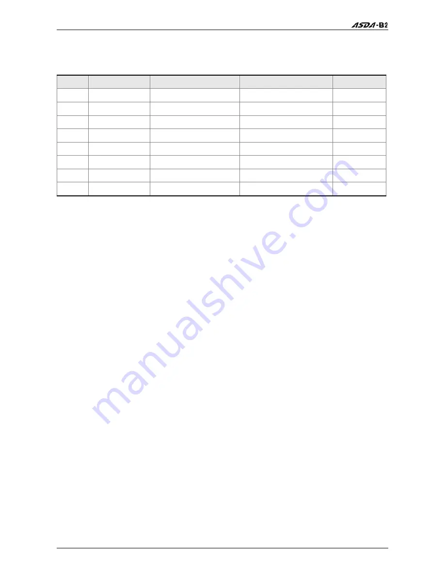
2.6 EMI Filter Selection
AC Servo Drive - EMI Filter Cross Reference
Item
Power
Servo Drive Model
Recommended EMI Filter
FootPrint
1 100W ASD-B2-0121-B
08TDT1W4S
N
2 200W ASD-B2-0221-B
08TDT1W4S
N
3 400W ASD-B2-0421-B
08TDT1W4S
N
4 750W ASD-B2-0721-B
20TDT1W4D
N
5 1000W ASD-B2-1021-B
20TDT1W4D
N
6 1500W ASD-B2-1521-B
20TDT1W4D
N
7 2000W ASD-B2-2023-B
20TDT1W4D
N
8 3000W ASD-B2-3023-B
20TDT1W4D
N
Installation
All electrical equipment, including AC servo drives, will generate high-frequency/low-
frequency noise and will interfere with peripheral equipment by radiation or conduction when
in operation. By using an EMI filter with correct installation, much of the interference can be
eliminated. It is recommended to use Delta’s EMI filter to have the best interference
elimination performance.
We assure that it can comply with following rules when AC servo drive and EMI filter are
installed and wired according to user manual:
EN61000-6-4 (2001)
EN61800-3 (2004) PDS of category C2
A2 (2007) Class A Group 1
General Precaution
To ensure the best interference elimination performance when using Delta’s EMI filter, please
follow the guidelines in this user manual to perform wiring and/or installation. In addition,
please also observe the following precautions:
EMI filter and AC servo drive should be installed on the same metal plate.
Please install AC servo drive on same footprint with EMI filter or install EMI filter as close
as possible to the AC servo drive.
All wiring should be as short as possible.
Metal plate should be grounded.
The cover of EMI filter and AC servo drive or grounding should be fixed on the metal plate
and the contact area should be as large as possible.
Содержание ASD-B2-0121-B
Страница 1: ......
Страница 13: ...Table of Contents xii Revision June 2010 This page intentionally left blank...
Страница 17: ...Chapter 1 Unpacking Check and Model Explanation 1 4 Revision June 2010 ECMA Series Servo Motor...
Страница 19: ...Chapter 1 Unpacking Check and Model Explanation 1 6 Revision June 2010 1 4 Servo Drive Features...
Страница 21: ...Chapter 1 Unpacking Check and Model Explanation 1 8 Revision June 2010 This page intentionally left blank...
Страница 25: ...Chapter 2 Installation and Storage 2 4 Revision June 2010 Minimum Clearances Side by Side Installation...
Страница 43: ...Chapter 3 Connections and Wiring 3 6 Revision June 2010 Figure 3 3 Three Phase Power Supply all models...
Страница 72: ...Chapter 3 Connections and Wiring Revision June 2010 3 35 3 5 2 Connection between PC and Connector CN3...
Страница 87: ...Chapter 4 Display and Operation 4 12 Revision June 2010 This page intentionally left blank...
Страница 100: ...Chapter 5 Trial Run and Tuning Procedure Revision June 2010 5 13 5 5 2 Load Inertia Estimation Flowchart...
Страница 131: ...Chapter 6 Control Modes of Operation 6 22 Revision June 2010 Time Domain...
Страница 153: ...Chapter 6 Control Modes of Operation 6 44 Revision June 2010 This page intentionally left blank...
Страница 267: ...Chapter 8 MODBUS Communications 8 18 Revision June 2010 This page intentionally left blank...
Страница 271: ...Chapter 9 Maintenance and Inspection 9 4 Revision June 2010 This page intentionally left blank...
Страница 291: ...Chapter 11 Specifications 11 8 Revision June 2010 11 3 Servo Motor Speed Torque Curves...


