Chapter 10 Troubleshooting
10-2
Revision June 2010
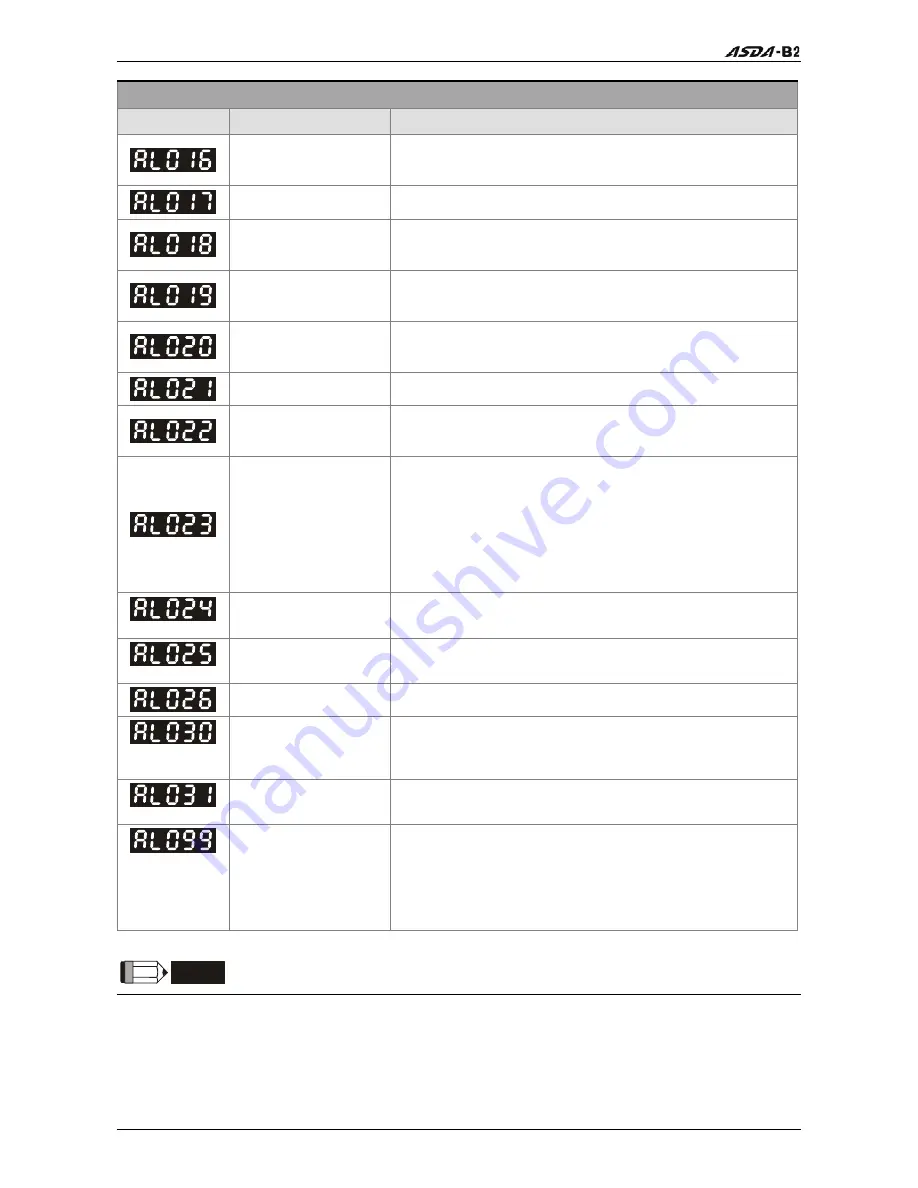
Fault Messages
Display
Fault Name
Fault Description
IGBT temperature
error
The temperature of IGBT is over high.
Memory error
EE-PROM write-in and read-out is in error.
Encoder output error
The encoder output exceeds the rated output
frequency.
Serial communication
error
RS232/485 communication is in error.
Serial communication
time out
RS232/485 communication time out.
Reserve Reserve
Input power phase
loss
One phase of the input power is loss.
Pre-overload warning
To warn that the servo motor and drive is going to
overload. This alarm will display before ALM06. When
the servo motor reach the setting value of P1-56, the
motor will send a warning to the drive. After the drive
has detected the warning, the DO signal OLW will be
activated and this fault message will display.
Encoder initial
magnetic field error
The magnetic field of the encoder U, V, W signal is in
error.
Encoder internal
error
The internal memory of the encoder is in error. An
internal counter error is detected.
Encoder data error
An encoder data error is detected for three times.
Motor protection
error
In order to protect the motor, this alarm will be
activated when the setting value of P1-57 is reached
after a period of time set by P1-58.
U,V,W wiring error
The wiring connections of U, V, W (for servo motor
output) and GND (for grounding) are in error.
DSP firmware
upgrade
EE-PROM is not reset after the firmware version is
upgraded.
This fault can be cleared after setting P2-08 to 30 first,
and then setting P2-08 to 28 next and restarting the
servo drive.
NOTE
1)
If there is any unknown fault code that is not listed on the above table, please inform the
distributor or contact with Delta for assistance.
Содержание ASD-B2-0121-B
Страница 1: ......
Страница 13: ...Table of Contents xii Revision June 2010 This page intentionally left blank...
Страница 17: ...Chapter 1 Unpacking Check and Model Explanation 1 4 Revision June 2010 ECMA Series Servo Motor...
Страница 19: ...Chapter 1 Unpacking Check and Model Explanation 1 6 Revision June 2010 1 4 Servo Drive Features...
Страница 21: ...Chapter 1 Unpacking Check and Model Explanation 1 8 Revision June 2010 This page intentionally left blank...
Страница 25: ...Chapter 2 Installation and Storage 2 4 Revision June 2010 Minimum Clearances Side by Side Installation...
Страница 43: ...Chapter 3 Connections and Wiring 3 6 Revision June 2010 Figure 3 3 Three Phase Power Supply all models...
Страница 72: ...Chapter 3 Connections and Wiring Revision June 2010 3 35 3 5 2 Connection between PC and Connector CN3...
Страница 87: ...Chapter 4 Display and Operation 4 12 Revision June 2010 This page intentionally left blank...
Страница 100: ...Chapter 5 Trial Run and Tuning Procedure Revision June 2010 5 13 5 5 2 Load Inertia Estimation Flowchart...
Страница 131: ...Chapter 6 Control Modes of Operation 6 22 Revision June 2010 Time Domain...
Страница 153: ...Chapter 6 Control Modes of Operation 6 44 Revision June 2010 This page intentionally left blank...
Страница 267: ...Chapter 8 MODBUS Communications 8 18 Revision June 2010 This page intentionally left blank...
Страница 271: ...Chapter 9 Maintenance and Inspection 9 4 Revision June 2010 This page intentionally left blank...
Страница 291: ...Chapter 11 Specifications 11 8 Revision June 2010 11 3 Servo Motor Speed Torque Curves...


