Chapter 5 Trial Run and Tuning Procedure
Revision June 2010
5-11
5.5 Tuning
Procedure
Estimate the ratio of Load Inertia to Servo Motor Inertia (J_load /J_motor): JOG Mode
Tuning Procedure
Display
1.
After wiring is completed, when power in connected to the AC servo
drive, the right side display will show on the LCD display.
2.
Press MODE key to enter into parameter mode.
3.
Press SHIFT key twice to select parameter group.
4.
Press UP key to view each parameter and select parameter P2-17.
5.
Press SET key to display the parameter value as shown on the right
side.
6.
Press SHIFT key twice to change the parameter values. Use UP key to
cycle through the available settings and then press SET key to
determine the parameter settings.
7.
Press UP key to view each parameter and select parameter P2-30.
8.
Press SET key to display the parameter value as shown on the right
side.
9.
Select parameter value 1. Use UP key to cycle through the available
settings.
10.
At this time, the servo drive is ON and the right side display will
appear next.
11.
Press DOWN key three times to select the ratio of Load Inertia to
Servo Motor Inertia (J_load /J_motor).
12.
Display the current ratio of Load Inertia to Servo Motor Inertia (J_load
/J_motor). (5.0 is default setting.)
13.
Press MODE key to select parameter mode.
14.
Press SHIFT key twice to select parameter group.
15.
Press UP key to select user parameter P4-05.
16.
Press SET key and JOG speed 20r/min will be displayed. Press UP and
DOWN key to increase and decrease JOG speed. To press SHIFT key
one time can add one digit number.
17.
Select desired JOG speed, press SET key and it will show the right
side display.
18.
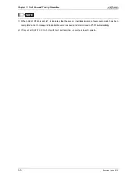
Pressing UP key is forward rotation and pressing DOWN key is reverse rotation.
19.
Execute JOG operation in low speed first. After the machine is running smoothly, then
execute JOG operation in high speed.
Содержание ASD-B2-0121-B
Страница 1: ......
Страница 13: ...Table of Contents xii Revision June 2010 This page intentionally left blank...
Страница 17: ...Chapter 1 Unpacking Check and Model Explanation 1 4 Revision June 2010 ECMA Series Servo Motor...
Страница 19: ...Chapter 1 Unpacking Check and Model Explanation 1 6 Revision June 2010 1 4 Servo Drive Features...
Страница 21: ...Chapter 1 Unpacking Check and Model Explanation 1 8 Revision June 2010 This page intentionally left blank...
Страница 25: ...Chapter 2 Installation and Storage 2 4 Revision June 2010 Minimum Clearances Side by Side Installation...
Страница 43: ...Chapter 3 Connections and Wiring 3 6 Revision June 2010 Figure 3 3 Three Phase Power Supply all models...
Страница 72: ...Chapter 3 Connections and Wiring Revision June 2010 3 35 3 5 2 Connection between PC and Connector CN3...
Страница 87: ...Chapter 4 Display and Operation 4 12 Revision June 2010 This page intentionally left blank...
Страница 100: ...Chapter 5 Trial Run and Tuning Procedure Revision June 2010 5 13 5 5 2 Load Inertia Estimation Flowchart...
Страница 131: ...Chapter 6 Control Modes of Operation 6 22 Revision June 2010 Time Domain...
Страница 153: ...Chapter 6 Control Modes of Operation 6 44 Revision June 2010 This page intentionally left blank...
Страница 267: ...Chapter 8 MODBUS Communications 8 18 Revision June 2010 This page intentionally left blank...
Страница 271: ...Chapter 9 Maintenance and Inspection 9 4 Revision June 2010 This page intentionally left blank...
Страница 291: ...Chapter 11 Specifications 11 8 Revision June 2010 11 3 Servo Motor Speed Torque Curves...


