Chapter 10 Troubleshooting
10-4
Revision June 2010
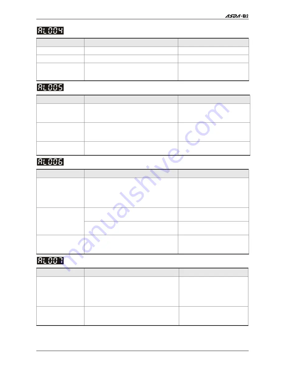
: Motor error
Potential Cause
Checking Method
Corrective Actions
Encoder is damage. Check Encoder for the damage.
Repair or replace the motor.
Encoder is loose.
Examine the Encoder connector.
Install the motor again.
The type of the
servo motor is
incorrect.
Check if the servo drive and servo motor
are not correctly matched for size (power
rating).
Replace the motor.
: Regeneration error
Potential Cause
Checking Method
Corrective Actions
Regenerative
resistor is not
connected.
Check the wiring connection of
regenerative resistor.
Reconnect regenerative
resistor.
Regenerative switch
transistor fault
Check if regenerative switch transistor is
short-circuited.
Please contact your distributor
for assistance or contact with
Delta.
Parameter setting is
in error
Confirm the parameter setting and
specifications of regenerative resistor.
Correctly reset parameter
again.
: Overload
Potential Cause
Checking Method
Corrective Actions
The drive has
exceeded its rated
load during
continuous
operation.
Check if the drive is overloaded.
Increase motor capacity or
reduce load.
Check if there is mechanical vibration
Adjust gain value of control
circuit.
Control system
parameter setting is
incorrect.
Accel/Decel time setting is too fast.
Decrease Accel/Decel time
setting.
The wiring of drive
and encoder is in
error.
Check the wiring of U, V, W and encoder. Ensure all wiring is correct.
: Overspeed
Potential Cause
Checking Method
Corrective Actions
Speed input
command is not
stable (too much
fluctuation).
Use signal detector to detect if input
signal is abnormal.
Ensure that input command
frequency is stable (not
fluctuate too much) and
activate filter function (P1-06,
P1-07 and P1-08).
Over-speed
parameter setting is
defective.
Check if over-speed parameter setting
value is too low.
Correctly set over-speed
parameter setting (P2-34).
Содержание ASD-B2-0121-B
Страница 1: ......
Страница 13: ...Table of Contents xii Revision June 2010 This page intentionally left blank...
Страница 17: ...Chapter 1 Unpacking Check and Model Explanation 1 4 Revision June 2010 ECMA Series Servo Motor...
Страница 19: ...Chapter 1 Unpacking Check and Model Explanation 1 6 Revision June 2010 1 4 Servo Drive Features...
Страница 21: ...Chapter 1 Unpacking Check and Model Explanation 1 8 Revision June 2010 This page intentionally left blank...
Страница 25: ...Chapter 2 Installation and Storage 2 4 Revision June 2010 Minimum Clearances Side by Side Installation...
Страница 43: ...Chapter 3 Connections and Wiring 3 6 Revision June 2010 Figure 3 3 Three Phase Power Supply all models...
Страница 72: ...Chapter 3 Connections and Wiring Revision June 2010 3 35 3 5 2 Connection between PC and Connector CN3...
Страница 87: ...Chapter 4 Display and Operation 4 12 Revision June 2010 This page intentionally left blank...
Страница 100: ...Chapter 5 Trial Run and Tuning Procedure Revision June 2010 5 13 5 5 2 Load Inertia Estimation Flowchart...
Страница 131: ...Chapter 6 Control Modes of Operation 6 22 Revision June 2010 Time Domain...
Страница 153: ...Chapter 6 Control Modes of Operation 6 44 Revision June 2010 This page intentionally left blank...
Страница 267: ...Chapter 8 MODBUS Communications 8 18 Revision June 2010 This page intentionally left blank...
Страница 271: ...Chapter 9 Maintenance and Inspection 9 4 Revision June 2010 This page intentionally left blank...
Страница 291: ...Chapter 11 Specifications 11 8 Revision June 2010 11 3 Servo Motor Speed Torque Curves...


