Chapter 8 MODBUS Communications
8-8
Revision June 2010
8.3 MODBUS
Communication
Protocol
When using RS-232/485 serial communication interface, each ASDA-B2 series AC servo drive
has a pre-assigned communication address specified by parameter “P3-00”. The computer
then controls each AC servo drive according to its communication address. ASDA-B2 series AC
servo drive can be set up to communicate on a MODBUS networks using on of the following
modes: ASCII (American Standard Code for Information Interchange) or RTU (Remote Terminal
Unit). Users can select the desired mode along with the serial port communication protocol in
parameter “P3-02”.
Code Description:
ASCII Mode:
Each 8-bit data is the combination of two ASCII characters. For example, a 1-byte data: 64 Hex,
shown as ‘64’ in ASCII, consists of ‘6’ (36Hex) and ‘4’ (34Hex).
The following table shows the available hexadecimal characters and their corresponding ASCII
codes.
Character
‘0’
‘1’
‘2’
‘3’
‘4’
‘5’
‘6’
‘7’
ASCII
code
30H 31H 32H 33H 34H 35H 36H 37H
Character
‘8’
‘9’
‘A’
‘B’
‘C’
‘D’
‘E’
‘F’
ASCII
code
38H 39H 41H 42H 43H 44H 45H 46H
RTU Mode:
Each 8-bit data is the combination of two 4-bit hexadecimal characters. For example, a 1-byte
data: 64 Hex.
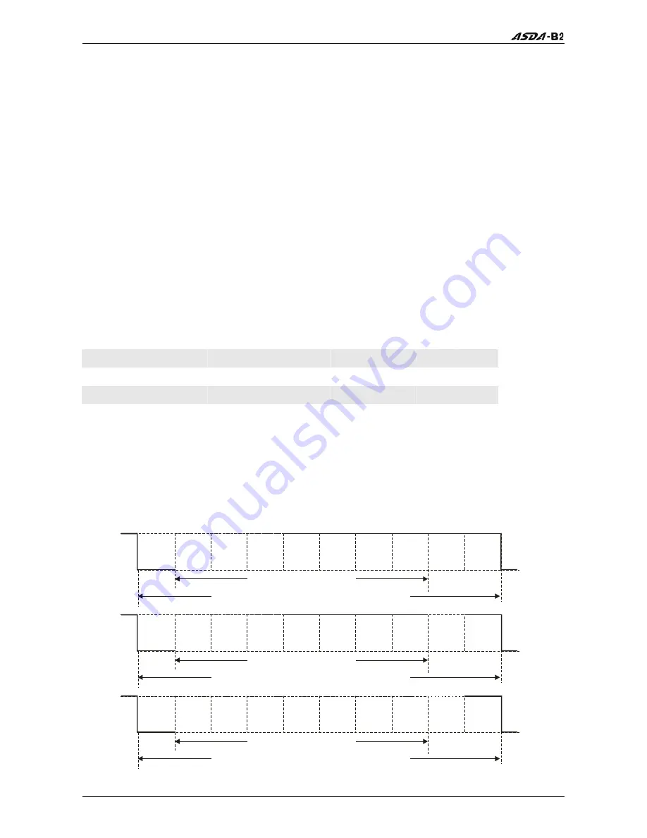
Data Format:
10-bit character frame (For 7-bit character)
7N2
Start
bit
0
1
2
3
4
5
6
Stop
bit
7-data bits
10-bits character frame
Stop
bit
7E1
Even
parity
Start
bit
0
1
2
3
4
5
6
Stop
bit
7-data bits
10-bits character frame
7O1
Odd
parity
Start
bit
0
1
2
3
4
5
6
Stop
bit
7-data bits
10-bits character frame
Содержание ASD-B2-0121-B
Страница 1: ......
Страница 13: ...Table of Contents xii Revision June 2010 This page intentionally left blank...
Страница 17: ...Chapter 1 Unpacking Check and Model Explanation 1 4 Revision June 2010 ECMA Series Servo Motor...
Страница 19: ...Chapter 1 Unpacking Check and Model Explanation 1 6 Revision June 2010 1 4 Servo Drive Features...
Страница 21: ...Chapter 1 Unpacking Check and Model Explanation 1 8 Revision June 2010 This page intentionally left blank...
Страница 25: ...Chapter 2 Installation and Storage 2 4 Revision June 2010 Minimum Clearances Side by Side Installation...
Страница 43: ...Chapter 3 Connections and Wiring 3 6 Revision June 2010 Figure 3 3 Three Phase Power Supply all models...
Страница 72: ...Chapter 3 Connections and Wiring Revision June 2010 3 35 3 5 2 Connection between PC and Connector CN3...
Страница 87: ...Chapter 4 Display and Operation 4 12 Revision June 2010 This page intentionally left blank...
Страница 100: ...Chapter 5 Trial Run and Tuning Procedure Revision June 2010 5 13 5 5 2 Load Inertia Estimation Flowchart...
Страница 131: ...Chapter 6 Control Modes of Operation 6 22 Revision June 2010 Time Domain...
Страница 153: ...Chapter 6 Control Modes of Operation 6 44 Revision June 2010 This page intentionally left blank...
Страница 267: ...Chapter 8 MODBUS Communications 8 18 Revision June 2010 This page intentionally left blank...
Страница 271: ...Chapter 9 Maintenance and Inspection 9 4 Revision June 2010 This page intentionally left blank...
Страница 291: ...Chapter 11 Specifications 11 8 Revision June 2010 11 3 Servo Motor Speed Torque Curves...


