Revision June 2010
10-1
Chapter 10 Troubleshooting
If a fault is detected on the servo drive or motor a corresponding fault code will be shown on
the drive's LED display. Fault codes can also be transmitted via communication, see P0-01 and
P4-00 ~ P4-04 for display on controller or HMI.
10.1 Fault Messages Table
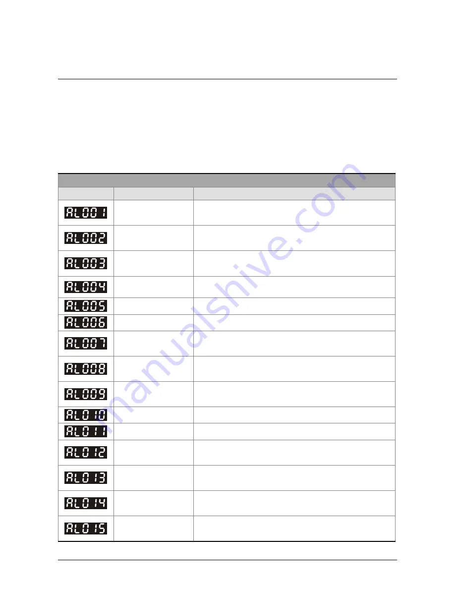
Servo Drive Fault Messages
Fault Messages
Display
Fault Name
Fault Description
Overcurrent
Main circuit current is higher than 1.5 multiple of
motor’s instantaneous maximum current value.
Overvoltage
Main circuit voltage has exceeded its maximum
allowable value.
Undervoltage
Main circuit voltage is below its minimum specified
value.
Motor error
The motor does not match the drive. They are not
correctly matched for size (power rating).
Regeneration error
Regeneration control operation is in error.
Overload
Servo motor and drive is overload.
Overspeed
Motor’s control speed exceeds the limit of normal
speed.
Abnormal pulse
control command
Input frequency of pulse command exceeds the limit of
its allowable setting value.
Excessive deviation
Position control deviation value exceeds the limit of its
allowable setting value.
Reserve Reserve
Encoder error
Pulse signal is in error.
Adjustment error
Adjusted value exceeds the limit of its allowable setting
value when perform electrical adjustment.
Emergency stop
activated
Emergency stop switch is activated.
Reverse limit switch
error
Reverse limit switch is activated.
Forward limit switch
error
Forward limit switch is activated.
Содержание ASD-B2-0121-B
Страница 1: ......
Страница 13: ...Table of Contents xii Revision June 2010 This page intentionally left blank...
Страница 17: ...Chapter 1 Unpacking Check and Model Explanation 1 4 Revision June 2010 ECMA Series Servo Motor...
Страница 19: ...Chapter 1 Unpacking Check and Model Explanation 1 6 Revision June 2010 1 4 Servo Drive Features...
Страница 21: ...Chapter 1 Unpacking Check and Model Explanation 1 8 Revision June 2010 This page intentionally left blank...
Страница 25: ...Chapter 2 Installation and Storage 2 4 Revision June 2010 Minimum Clearances Side by Side Installation...
Страница 43: ...Chapter 3 Connections and Wiring 3 6 Revision June 2010 Figure 3 3 Three Phase Power Supply all models...
Страница 72: ...Chapter 3 Connections and Wiring Revision June 2010 3 35 3 5 2 Connection between PC and Connector CN3...
Страница 87: ...Chapter 4 Display and Operation 4 12 Revision June 2010 This page intentionally left blank...
Страница 100: ...Chapter 5 Trial Run and Tuning Procedure Revision June 2010 5 13 5 5 2 Load Inertia Estimation Flowchart...
Страница 131: ...Chapter 6 Control Modes of Operation 6 22 Revision June 2010 Time Domain...
Страница 153: ...Chapter 6 Control Modes of Operation 6 44 Revision June 2010 This page intentionally left blank...
Страница 267: ...Chapter 8 MODBUS Communications 8 18 Revision June 2010 This page intentionally left blank...
Страница 271: ...Chapter 9 Maintenance and Inspection 9 4 Revision June 2010 This page intentionally left blank...
Страница 291: ...Chapter 11 Specifications 11 8 Revision June 2010 11 3 Servo Motor Speed Torque Curves...


