


Chapter 7 Servo Parameters
Revision June 2010
7-79
Please note:
1.
This adjustment function is enabled after parameter P2-08 is set to 20.
2.
When executing any adjustment, the external wiring connected to analog
speed or torque must be removed and the servo system should be off (Servo
off).
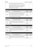
P4 - 11
SOF1
Analog Speed Input Drift Adjustment 1
Address: 0416H, 0417H
Default: Factory setting
Related Section: N/A
Applicable Control Mode: ALL
Unit: N/A
Range: 0 ~ 32767
Data Size: 16-bit
Display Format: Decimal
Settings:
The adjustment functions from P4-11 through P4-19 are enabled after parameter
P2-08 is set to 22. Although these parameters allow the users to execute manual
adjustment, we still do not recommend the users to change the default setting
value of these parameters (P4-11 ~ P4-19) manually.
Please note that when P2-08 is set to 10, the users cannot reset this parameter.
P4 - 12
SOF2
Analog Speed Input Drift Adjustment 2
Address: 0418H, 0419H
Default: Factory setting
Related Section: N/A
Applicable Control Mode: ALL
Unit: N/A
Range: 0 ~ 32767
Data Size: 16-bit
Display Format: Decimal
Settings:
Refer to P4-11 for explanation.
Please note that when P2-08 is set to 10, the users cannot reset this parameter.
P4 - 13
TOF1
Analog Torque Drift Adjustment 1
Address: 041AH, 041BH
Default: Factory setting
Related Section: N/A
Applicable Control Mode: ALL
Unit: N/A
Range: 0 ~ 32767
Data Size: 16-bit
Display Format: Decimal
Settings:
Содержание ASD-B2-0121-B
Страница 1: ......
Страница 13: ...Table of Contents xii Revision June 2010 This page intentionally left blank...
Страница 17: ...Chapter 1 Unpacking Check and Model Explanation 1 4 Revision June 2010 ECMA Series Servo Motor...
Страница 19: ...Chapter 1 Unpacking Check and Model Explanation 1 6 Revision June 2010 1 4 Servo Drive Features...
Страница 21: ...Chapter 1 Unpacking Check and Model Explanation 1 8 Revision June 2010 This page intentionally left blank...
Страница 25: ...Chapter 2 Installation and Storage 2 4 Revision June 2010 Minimum Clearances Side by Side Installation...
Страница 43: ...Chapter 3 Connections and Wiring 3 6 Revision June 2010 Figure 3 3 Three Phase Power Supply all models...
Страница 72: ...Chapter 3 Connections and Wiring Revision June 2010 3 35 3 5 2 Connection between PC and Connector CN3...
Страница 87: ...Chapter 4 Display and Operation 4 12 Revision June 2010 This page intentionally left blank...
Страница 100: ...Chapter 5 Trial Run and Tuning Procedure Revision June 2010 5 13 5 5 2 Load Inertia Estimation Flowchart...
Страница 131: ...Chapter 6 Control Modes of Operation 6 22 Revision June 2010 Time Domain...
Страница 153: ...Chapter 6 Control Modes of Operation 6 44 Revision June 2010 This page intentionally left blank...
Страница 267: ...Chapter 8 MODBUS Communications 8 18 Revision June 2010 This page intentionally left blank...
Страница 271: ...Chapter 9 Maintenance and Inspection 9 4 Revision June 2010 This page intentionally left blank...
Страница 291: ...Chapter 11 Specifications 11 8 Revision June 2010 11 3 Servo Motor Speed Torque Curves...