3: Audio/Filter Board
3-6
PRC1099A-MS
3.1.3
ALC Circuit
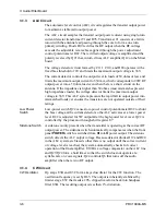
The automatic level control (ALC) circuit regulates the transmit output power
to maintain a stable radio output power.
The ALC circuit samples the transmit output power current using single-turn
current detector transformer T1and R76. Transformer T1 consists of a ferrite
toroid with the antenna lead passing through the core to form a one turn
primary winding. Diode D19 rectifies the RF output when the RF voltage
exceeds the adjustable reverse bias applied through the power adjustment
control potentiometer R82. The rectified output voltage is amplified and the
polarity reversed by Q21 that, in turn, drives ALC amplifier Q12 on the Mixer
board.
The voltage detector circuit formed by C111, C110, and D20 operates with a
fixed bias threshold of 8V and limits the maximum output voltage to 36V.
The current detector controls the output level in loads of 50 ohms or less and
limits the maximum output current to 630 mA, which corresponds to 20W RF
output power into a 50 ohm load even when there is a short circuit on the
antenna. If the impedance is higher than 50 ohms (most mismatches present
high impedance loads), the voltage detector limits the maximum output
voltage to 36V. This ALC system prevents the rapid fall in output power into
mismatched loads yet ensures the transistors are not operated outside of their
ratings.
Low Power
Switch
Low-power switch Q22 causes low-power control potentiometer R82 to shunt
the bias voltage at the current detector so the ALC activates at a lower power
level. R82 is adjusted for 5W output after the high-power level is set. Q22 is
controlled by the processor through shift register U7.
Sidetone Switch
A sidetone is only present when the transmitter is operating at the correct RF
output power. The sidetone switch automatically compensates when the front
panel
POWER
switch is switched from
HI
to
LO
power output. The sidetone
switch detects the ALC output voltage. Because detector diodes D19 and D20
in the ALC system are biased so that there is no output until the correct current
or voltage level is reached, the system automatically checks for correct
operation of the final amplifier. U10B is a voltage comparator on the ALC line
and Q23/Q24 form a hold timer so that the switch does not operate at a
syllabic rate on voice signals. Q24 controls Q6 that turns off the audio
amplifier when there is no RF output.
3.1.4
CW Circuit
CW Oscillator
Op amps U3B and U3C form a keyed oscillator for the CW function. The
oscillation frequency is set by R65. The output is inherently stabilized by
limiter stage U3C that feeds a 20% clipped waveform back into bandpass
filter U3B. The resulting output is less than 1% distortion.
Содержание PRC1099A
Страница 4: ......
Страница 8: ......
Страница 35: ......
Страница 49: ...3 Audio Filter Board 3 14 PRC1099A MS Figure 3 2 Audio Filter Board Component Locations 738221 Rev J ...
Страница 65: ......
Страница 71: ...4 1650 kHz IF Board 4 6 PRC1099A MS Figure 4 2 1650 kHz IF Board Component Locations 738028 Rev D ...
Страница 76: ......
Страница 86: ...5 Mixer Board 5 10 PRC1099A MS Figure 5 4 Mixer Board Component Locations 738217 Rev H ...
Страница 97: ......
Страница 103: ...6 Power Amplifier Board 6 6 PRC1099A MS Figure 6 2 Power Amplifier Board Component Locations 738617 Rev C ...
Страница 117: ...7 Antenna Tuner Board PRC1099A MS 7 9 Figure 7 2 Antenna Tuner Driver Board Component Locations 738346 Rev B ...
Страница 118: ...7 Antenna Tuner Board 7 10 PRC1099A MS Figure 7 3 Antenna Tuner Board Component Locations 738027 Rev D ...
Страница 125: ......
Страница 131: ...8 Synthesizer Board 8 6 PRC1099A MS Figure 8 2 Synthesizer Board Component Locations 738025 Rev A ...
Страница 163: ...9 Processor Board 9 14 PRC1099A MS Figure 9 2 Processor Board Component Locations 738218 Rev B ...
Страница 178: ...10 Display Board 10 8 PRC1099A MS Figure 10 1 Display Board Component Location Diagram 738220 Rev G ...
Страница 181: ......
Страница 185: ...11 Junction Board 11 4 PRC1099A MS Figure 11 1 Junction Board Component Locations 738222 Rev F ...
Страница 200: ......
Страница 207: ...13 Internal Options PRC1099A MS 13 7 Figure 13 3 ALE Board Component Locations 1 of 2 738215 Rev B ...
Страница 208: ...13 Internal Options 13 8 PRC1099A MS Figure 13 4 ALE Board Component Locations 2 of 2 738215 Rev B ...
Страница 241: ......
Страница 247: ...Index 6 T Technical specifications 1 2 Transmit path 2 4 U USB 1 4 see also Modulation modes USB LSB mode V VSWR 1 4 ...


