7: Antenna Tuner Board
PRC1099A-MS
7-7
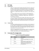
7.2
RF Paths
7.2.1
Receive Path
The receive signal from the front panel whip antenna connector is received on
the hard wire (white) input to the Antenna Tuner board. It is routed through
the tuning network of inductors and capacitors. It then passes through current
detector T1 and impedance transformer T2 and then bypasses the 10 dB
attenuator. It is output through onboard coax connector J3 to the Audio Filter
board.
The receive signal can also be received from the 50 ohm load input and is
received through the coax connection in connector J2. It is routed directly to
onboard coax connector J3, bypassing the tuning network, current detector,
and impedance transformer.
A relay switch mounted inside the front panel whip antenna connector notifies
the processor whether or not an antenna is connected to the whip antenna
connector. If not, the ANT SW signal activates relays K15 and K16 to switch
the receive signal between the whip antenna path and the 50 ohm connector
path.
7.2.2
Transmit Path
The transmit path through the Antenna Tuner board is exactly the opposite of
the receive path. The transmit path is received at onboard connector J3 from
the Audio Filter board and is switched to either the whip antenna connector or
the 50 ohm connector. From J3, the transmit signal to the 50 ohm connector is
routed directly to the coax connector in J2.
From J3, the transmit signal to the whip antenna connector is routed through
impedance transformer T2, current detector transformer T1, the tuning
network, and out the hard wire to the whip antenna connector.
7.3
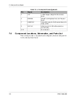
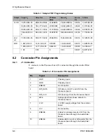
Connector Pin Assignments
The Antenna Tuner board includes the following connections.
Table 7-2 J1 Connector Pin Assignments
Pin
Signal
Description
1
GND
Ground.
2
+12V
+12 VDC supply voltage from the Junction
board.
3
DATA
Matching element selection data to shift
registers from the Processor board.
4
CLOCK
Clock pulse to shift registers from the
Processor board.
Содержание PRC1099A
Страница 4: ......
Страница 8: ......
Страница 35: ......
Страница 49: ...3 Audio Filter Board 3 14 PRC1099A MS Figure 3 2 Audio Filter Board Component Locations 738221 Rev J ...
Страница 65: ......
Страница 71: ...4 1650 kHz IF Board 4 6 PRC1099A MS Figure 4 2 1650 kHz IF Board Component Locations 738028 Rev D ...
Страница 76: ......
Страница 86: ...5 Mixer Board 5 10 PRC1099A MS Figure 5 4 Mixer Board Component Locations 738217 Rev H ...
Страница 97: ......
Страница 103: ...6 Power Amplifier Board 6 6 PRC1099A MS Figure 6 2 Power Amplifier Board Component Locations 738617 Rev C ...
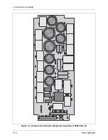
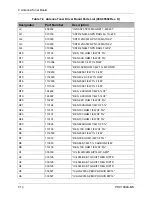
Страница 117: ...7 Antenna Tuner Board PRC1099A MS 7 9 Figure 7 2 Antenna Tuner Driver Board Component Locations 738346 Rev B ...
Страница 118: ...7 Antenna Tuner Board 7 10 PRC1099A MS Figure 7 3 Antenna Tuner Board Component Locations 738027 Rev D ...
Страница 125: ......
Страница 131: ...8 Synthesizer Board 8 6 PRC1099A MS Figure 8 2 Synthesizer Board Component Locations 738025 Rev A ...
Страница 163: ...9 Processor Board 9 14 PRC1099A MS Figure 9 2 Processor Board Component Locations 738218 Rev B ...
Страница 178: ...10 Display Board 10 8 PRC1099A MS Figure 10 1 Display Board Component Location Diagram 738220 Rev G ...
Страница 181: ......
Страница 185: ...11 Junction Board 11 4 PRC1099A MS Figure 11 1 Junction Board Component Locations 738222 Rev F ...
Страница 200: ......
Страница 207: ...13 Internal Options PRC1099A MS 13 7 Figure 13 3 ALE Board Component Locations 1 of 2 738215 Rev B ...
Страница 208: ...13 Internal Options 13 8 PRC1099A MS Figure 13 4 ALE Board Component Locations 2 of 2 738215 Rev B ...
Страница 241: ......
Страница 247: ...Index 6 T Technical specifications 1 2 Transmit path 2 4 U USB 1 4 see also Modulation modes USB LSB mode V VSWR 1 4 ...


