7: Antenna Tuner Board
PRC1099A-MS
7-3
7.1.5
Binary Sequenced Inductors
To resonate the whip antenna at 2 MHz requires an inductance of
approximately 168
H, therefore it must be possible to vary the inductance
from 0 to 168
H. The best solution is a series of inductors, switched in and
out of circuit in a binary progression. The tuning program starts with L1, a
0.33
H inductor, and doubles the size of each inductor up to 84
H, making it
possible to change the inductance in 0.33
H steps from 0 (zero) up to 168
H
using only nine inductors. The tuner uses ten inductors, since it is necessary to
use two separate 44
H inductors, L9 and L10, for the final inductance step.
When using the whip antenna, very high voltages are generated at maximum
inductance. To prevent possible RF burns to the operator, the power is
automatically reduced when inductors L8, L9, and L10 are in circuit. This
keeps the maximum output voltage from exceeding approximately 1000V.
7.1.6
Shunt Capacitors
The tuning program uses shunt capacitors C1 and C2 when the antenna
exhibits inductive reactance. These capacitors give 50 to 150 pF in 50 pF
steps. The tuner uses the minimum step size that causes the antenna to appear
capacitive and cancels the remaining reactance with series inductance. The
capacitors are connected between L6 and L7 to minimize the effects of stray
capacitance and reduce the required voltage rating.
Figure 7-1 Antenna Tuner Board Block Diagram
Whip Antenna
200 µ
C1
C2
Series
Capacitor
C5
Shunt
Capacitors
Clock
Strobe
Data
Antenna
Switch
S3
(off board)
To
Processor
J3
50 ohm
Out
50 µ
12.5 µ
Impedance
Transformer
Binary Sequenced
Inductors
0.25 µH to 168 µH
Relay Drivers
K1 to K16
Comparator
D/A
Decoder
Serial
Decoder
Serial
Decoder
Current
Detector
J2
50 ohm
In
10 dB
Att
enu
ator
K17A
K15A
K15B
K16B
Содержание PRC1099A
Страница 4: ......
Страница 8: ......
Страница 35: ......
Страница 49: ...3 Audio Filter Board 3 14 PRC1099A MS Figure 3 2 Audio Filter Board Component Locations 738221 Rev J ...
Страница 65: ......
Страница 71: ...4 1650 kHz IF Board 4 6 PRC1099A MS Figure 4 2 1650 kHz IF Board Component Locations 738028 Rev D ...
Страница 76: ......
Страница 86: ...5 Mixer Board 5 10 PRC1099A MS Figure 5 4 Mixer Board Component Locations 738217 Rev H ...
Страница 97: ......
Страница 103: ...6 Power Amplifier Board 6 6 PRC1099A MS Figure 6 2 Power Amplifier Board Component Locations 738617 Rev C ...
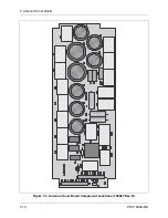
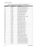
Страница 117: ...7 Antenna Tuner Board PRC1099A MS 7 9 Figure 7 2 Antenna Tuner Driver Board Component Locations 738346 Rev B ...
Страница 118: ...7 Antenna Tuner Board 7 10 PRC1099A MS Figure 7 3 Antenna Tuner Board Component Locations 738027 Rev D ...
Страница 125: ......
Страница 131: ...8 Synthesizer Board 8 6 PRC1099A MS Figure 8 2 Synthesizer Board Component Locations 738025 Rev A ...
Страница 163: ...9 Processor Board 9 14 PRC1099A MS Figure 9 2 Processor Board Component Locations 738218 Rev B ...
Страница 178: ...10 Display Board 10 8 PRC1099A MS Figure 10 1 Display Board Component Location Diagram 738220 Rev G ...
Страница 181: ......
Страница 185: ...11 Junction Board 11 4 PRC1099A MS Figure 11 1 Junction Board Component Locations 738222 Rev F ...
Страница 200: ......
Страница 207: ...13 Internal Options PRC1099A MS 13 7 Figure 13 3 ALE Board Component Locations 1 of 2 738215 Rev B ...
Страница 208: ...13 Internal Options 13 8 PRC1099A MS Figure 13 4 ALE Board Component Locations 2 of 2 738215 Rev B ...
Страница 241: ......
Страница 247: ...Index 6 T Technical specifications 1 2 Transmit path 2 4 U USB 1 4 see also Modulation modes USB LSB mode V VSWR 1 4 ...


