9: Processor Board
PRC1099A-MS
9-7
BITE ON
is displayed on the front panel LCD. The BITE program
begins stepping through each test routine and stops if a failure occurs
(except with tests requiring operator interaction).
A failure results in the display of an error message.
CAUTION: Do not press PTT when performing BITE tests.
BITE Test
Descriptions
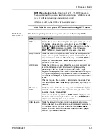
The following table provides the sequence of tests performed by BITE.
Test
Description
Battery
Reads the battery voltage using the analog converter system. If
the battery voltage is below the minimum level of 11V,
BAT
LOW
is displayed and BITE stops. If the battery voltage is above
15V,
BAT HIGH
is displayed and BITE stops. Otherwise,
BAT PASS
is displayed and BITE proceeds to next test.
Whip Antenna
Tests the antenna whip switch and verifies that a whip antenna
or antenna adapter is installed (required for transmitter tests). If
an antenna is not installed, BITE fails, stops, and
ANT FAIL
is
displayed. Otherwise,
ANT PASS
is displayed and BITE
proceeds to next test.
LCD Display
Tests the LCD display and verifies that each digit, segment, and
icon functions properly. BITE tests each digit/segment by
performing a walking digit test in which the entire 14 digit
segment is displayed on the left and then shifted over one digit to
the right, through all eight digit positions. A second test exercises
the colons of the display by shifting a colon. A third test shifts the
icons.
This test requires the operator to determine test pass/fail. When
test is completed,
DIS PASS
is displayed and BITE proceeds to
next test.
Processor
RAM
Performs a non-destructive memory test on static RAM chips U4
and U5 that writes and reads selected test bit patterns to insure
integrity of battery backup RAM.
Upon any read/write cycle failure,
RAM FAIL
is displayed and
BITE stops. If no memory test error is detected,
RAM PASS
is
displayed and BITE proceeds to next test.
USB Receiver
Tests the receiver circuitry of radio in upper sideband mode.
During this test, an audible tone is heard for at least 2 seconds in
the handset. If BITE does not detect the tone,
USB FAIL
is
displayed and BITE stops. Otherwise, USB PASS is displayed
and BITE proceeds to next test.
Содержание PRC1099A
Страница 4: ......
Страница 8: ......
Страница 35: ......
Страница 49: ...3 Audio Filter Board 3 14 PRC1099A MS Figure 3 2 Audio Filter Board Component Locations 738221 Rev J ...
Страница 65: ......
Страница 71: ...4 1650 kHz IF Board 4 6 PRC1099A MS Figure 4 2 1650 kHz IF Board Component Locations 738028 Rev D ...
Страница 76: ......
Страница 86: ...5 Mixer Board 5 10 PRC1099A MS Figure 5 4 Mixer Board Component Locations 738217 Rev H ...
Страница 97: ......
Страница 103: ...6 Power Amplifier Board 6 6 PRC1099A MS Figure 6 2 Power Amplifier Board Component Locations 738617 Rev C ...
Страница 117: ...7 Antenna Tuner Board PRC1099A MS 7 9 Figure 7 2 Antenna Tuner Driver Board Component Locations 738346 Rev B ...
Страница 118: ...7 Antenna Tuner Board 7 10 PRC1099A MS Figure 7 3 Antenna Tuner Board Component Locations 738027 Rev D ...
Страница 125: ......
Страница 131: ...8 Synthesizer Board 8 6 PRC1099A MS Figure 8 2 Synthesizer Board Component Locations 738025 Rev A ...
Страница 163: ...9 Processor Board 9 14 PRC1099A MS Figure 9 2 Processor Board Component Locations 738218 Rev B ...
Страница 178: ...10 Display Board 10 8 PRC1099A MS Figure 10 1 Display Board Component Location Diagram 738220 Rev G ...
Страница 181: ......
Страница 185: ...11 Junction Board 11 4 PRC1099A MS Figure 11 1 Junction Board Component Locations 738222 Rev F ...
Страница 200: ......
Страница 207: ...13 Internal Options PRC1099A MS 13 7 Figure 13 3 ALE Board Component Locations 1 of 2 738215 Rev B ...
Страница 208: ...13 Internal Options 13 8 PRC1099A MS Figure 13 4 ALE Board Component Locations 2 of 2 738215 Rev B ...
Страница 241: ......
Страница 247: ...Index 6 T Technical specifications 1 2 Transmit path 2 4 U USB 1 4 see also Modulation modes USB LSB mode V VSWR 1 4 ...


