12: Front Panel Assembly
12-6
PRC1099A-MS
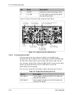
The
TUNE
switch works the same way as the
DIGIT
switch. When you press
up on the
TUNE
switch, the SLEWUP line is grounded through the
TUNE
switch center conductor. This signal in normally pulled high (+5V) on the
Processor board. The processor reads the low line level at U14 on the
Processor board and increments the display on the Display board to the next
frequency digit, channel number, or option menu item. When you press down
on the
DIGIT
switch, the SLEWDN line is grounded, the processor reads the
change and decrements the display to the next frequency digit, channel
number, or option menu item.
12.1.5
Whip Tune Button
The
Whip Tune
button initiates an antenna tune sequence, saving changes
made to radio settings, and activating the BITE feature.
Note:
This applies to the internal as well as an installed external antenna
tuner (when the antenna tuner is selected in
TUNER
under the
OPTION
menu).
Figure 12-5 Digit and Tune Switches Diagram
SLEW DN
SLEW UP
DIGITUP
DIGITDN
DIGIT
TUNE
Processor
Board
+5V
25
19
6
5
J5
U14
U1
Processor
Position
Description
Momentary Press
Activates automatic antenna tuner to tune whip or long wire
antennas.
Press and
Momentary Hold
Saves and stores frequencies, channels and menu
settings.
Press and Turn on
Transceiver
Activates BITE (Built-In-Test-Equipment).
Содержание PRC1099A
Страница 4: ......
Страница 8: ......
Страница 35: ......
Страница 49: ...3 Audio Filter Board 3 14 PRC1099A MS Figure 3 2 Audio Filter Board Component Locations 738221 Rev J ...
Страница 65: ......
Страница 71: ...4 1650 kHz IF Board 4 6 PRC1099A MS Figure 4 2 1650 kHz IF Board Component Locations 738028 Rev D ...
Страница 76: ......
Страница 86: ...5 Mixer Board 5 10 PRC1099A MS Figure 5 4 Mixer Board Component Locations 738217 Rev H ...
Страница 97: ......
Страница 103: ...6 Power Amplifier Board 6 6 PRC1099A MS Figure 6 2 Power Amplifier Board Component Locations 738617 Rev C ...
Страница 117: ...7 Antenna Tuner Board PRC1099A MS 7 9 Figure 7 2 Antenna Tuner Driver Board Component Locations 738346 Rev B ...
Страница 118: ...7 Antenna Tuner Board 7 10 PRC1099A MS Figure 7 3 Antenna Tuner Board Component Locations 738027 Rev D ...
Страница 125: ......
Страница 131: ...8 Synthesizer Board 8 6 PRC1099A MS Figure 8 2 Synthesizer Board Component Locations 738025 Rev A ...
Страница 163: ...9 Processor Board 9 14 PRC1099A MS Figure 9 2 Processor Board Component Locations 738218 Rev B ...
Страница 178: ...10 Display Board 10 8 PRC1099A MS Figure 10 1 Display Board Component Location Diagram 738220 Rev G ...
Страница 181: ......
Страница 185: ...11 Junction Board 11 4 PRC1099A MS Figure 11 1 Junction Board Component Locations 738222 Rev F ...
Страница 200: ......
Страница 207: ...13 Internal Options PRC1099A MS 13 7 Figure 13 3 ALE Board Component Locations 1 of 2 738215 Rev B ...
Страница 208: ...13 Internal Options 13 8 PRC1099A MS Figure 13 4 ALE Board Component Locations 2 of 2 738215 Rev B ...
Страница 241: ......
Страница 247: ...Index 6 T Technical specifications 1 2 Transmit path 2 4 U USB 1 4 see also Modulation modes USB LSB mode V VSWR 1 4 ...


